Other news

What is Antenna Gain in Satellite Communications? (Explained simply)
Read more
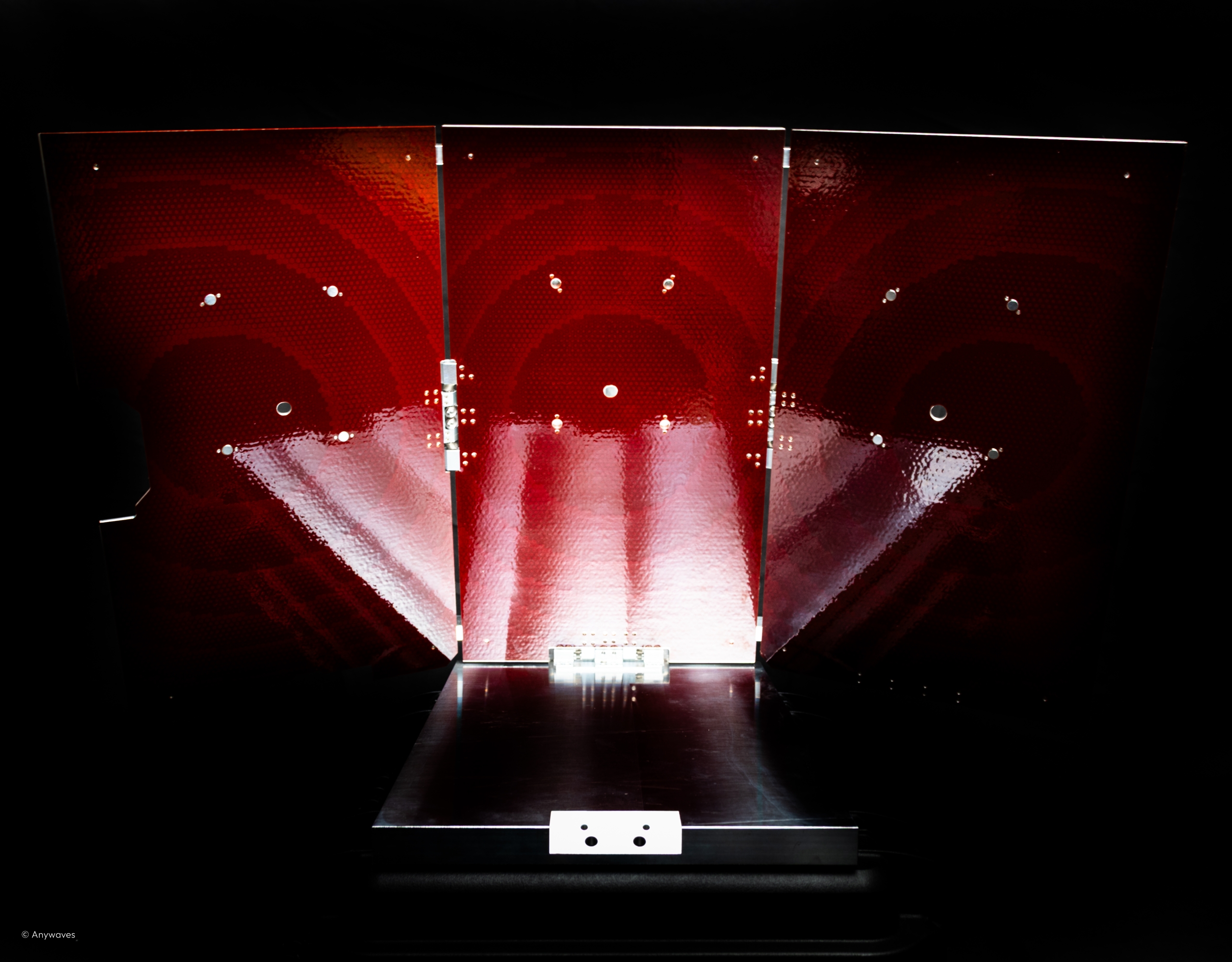
Reflectarray Antennas for Small Satellites: From Concept to First Commercial Deployment
Read more
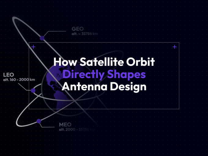
When we talk about satellite antennas, it’s easy to focus on frequency bands, link budgets, or gain figures. But behind every antenna sits an even more fundamental design driver: the orbit. Whether a spacecraft operates in Low Earth Orbit (LEO), Medium Earth Orbit (MEO), Geostationary Orbit (GEO), or even deep space, its orbital altitude and dynamics impose very specific — and sometimes dramatically different — constraints on antenna architecture.
In this article, we take a detailed look at how orbit selection impacts space antenna design. You’ll see why an antenna designed for GEO may not survive in LEO, why LEO isn’t always “easier”, and why environmental effects can be as limiting as RF performance itself.

For most satellite systems, the mission starts with a single foundational decision: what orbit will you fly in? Whether you’re developing an Earth observation cubesat, a MEO navigation platform or a GEO telecom satellite, the choice of orbit acts as a design constraint that will ripple across every subsystem — and antennas are among the most directly affected.
From RF link requirements to mechanical structure, from thermal stress to lifetime expectations, the orbit defines the framework within which the antenna must perform. Let’s break this down into core dimensions.
Let’s first establish a quick comparative overview of the main orbital regimes:
| Orbit | Altitude Range | Typical Applications |
| LEO (Low Earth Orbit) | 160 – 2,000 km | Earth Observation, IoT, Cubesats, Constellations (e.g. Starlink, OneWeb) |
| MEO (Medium Earth Orbit) | 2,000 – 35,786 km | GNSS (GPS, Galileo, GLONASS), Some data relay systems |
| GEO (Geostationary Orbit) | ~35,786 km | Telecommunications, TV broadcast, Weather satellites |
| Deep Space / Interplanetary | Beyond GEO | Planetary exploration, lunar missions, scientific probes |
Each orbit comes with a unique mix of operational geometry and environmental exposure — both of which directly influence antenna performance and survivability..
The most immediate impact of orbital altitude is link distance, which drives free-space path loss (FSPL) — a fundamental RF parameter. FSPL grows with both distance and frequency, according to:
![]()
Where:
This formula means a system operating in GEO (~36,000 km) suffers 37 dB more path loss than a comparable system in LEO at 500 km.
Indeed, the higher the orbit, the larger the link distance, and the greater the free-space path loss (FSPL).
These differences are not minor — a 50 dB increase in FSPL from LEO to GEO equates to a 100,000x drop in received power if antenna gain and transmit power remain constant.
To close the link, you must compensate with:
But antenna gain and beamwidth are two sides of the same coin. As we increase gain to fight path loss, we narrow the beam — which makes pointing accuracy and coverage strategy even more critical.
Once link distance is defined by orbit, the next challenge is how to direct the signal. Antenna gain is intrinsically linked to beamwidth: higher gain means a narrower beam — and that influences everything from footprint coverage to pointing tolerances.
Key rule:
In LEO, flexibility and agility are the priority.
In GEO, precision and long-term stability dominate.
The narrower the beam, the harder it is to keep it on target — which leads us to the next essential challenge: how do we track and steer that beam in orbit?
As soon as beam direction becomes critical, tracking strategy enters the equation. The relative motion between the satellite and its ground target determines how the beam must behave over time — whether it stays fixed, must be steered, or actively tracked in real time.
Different orbits mean different motion dynamics:
In short: the lower the orbit, the more dynamic the tracking, and the more the antenna system must compensate in real time.
But even if you have the right RF architecture, beam coverage, and tracking logic, none of it matters if the antenna can’t fit on the spacecraft — or withstand both the mechanical stress of launch and the harsh operational environment of space. That’s where packaging, materials, and deployment come into play.
Antenna design must align with not only RF performance goals but also mechanical and launch constraints.
Mass, stowed volume, and integration envelope vary significantly between orbits — and directly influence which antenna architectures are viable.
LEO missions, particularly CubeSats and smallsats, are often launched as secondary payloads. This imposes strict packaging rules: antennas must conform to rideshare deployment specifications, with minimal protrusion and efficient folding mechanisms.
Planar antennas, deployable monopoles, and hinged panels are widely used. These designs prioritize compactness and simplicity, even at the cost of lower gain or less flexibility.
GEO and interplanetary platforms generally offer more physical volume and mass margin for larger antennas — such as reflectors, boom-fed structures, or articulated phased arrays.
But with that added space comes greater risk. Mechanical robustness and long-term dimensional stability become critical, especially for missions lasting 10–15+ years.
More complex environmental factors (radiation, thermal deformation, material compatibility) will be addressed in the next section.
Once deployed in space, antennas are exposed to intense thermal variations — and the nature of those variations depends on orbit. This isn’t just about heat; it’s about how materials behave under constant stress.
To ensure long-term reliability, Anywaves antennas undergo two thermal qualification campaigns:
These procedures are critical to verifying both short-term survivability and long-term durability under real operational stress.
Thermal fatigue is just one of the invisible killers. In many missions, especially beyond LEO, radiation exposure becomes equally — if not more — decisive.
Radiation isn’t just a consideration for electronics. It has direct consequences on antenna structure, coatings, dielectric materials, and long-term RF stability.
Radiation and thermal stress contribute to different failure modes in spacecraft systems. Radiation can degrade adhesives, composites, and polymers, reducing their mechanical strength and long-term stability. Separately, repeated thermal cycling drives failures at interfaces where materials have mismatched coefficients of thermal expansion (CTE), such as in composite assemblies or bonded joints. The combination of radiation-induced material degradation and thermal stress can make such interfaces more prone to failure over time. For this reason, metallic and monolithic architectures are often preferred in high-radiation or long-duration missions. Radiation also determines which materials can be used, how long they will last, and whether RF performance remains stable — all of which depend on orbit and are critical to mission success.
Every orbit brings its own timeline — and antenna reliability must match or exceed the mission duration. This includes mechanical survivability, RF performance consistency, and environmental resistance over time.
| Orbit | Typical Mission Duration |
| LEO | 3–8 years |
| MEO | 10–15 years |
| GEO | 15+ years |
| Deep Space | Multi-year to multi-decade, no servicing |
As we’ve explained in the previous sections, over such timescales, RF drift can come from multiple sources:
Antenna engineers must account not just for “Day 1 performance”, but for long-term RF and structural integrity — often with no opportunity for correction.
Whether you’re designing for a 5-year LEO mission or a 20-year GEO platform, the reliability margin must be built into the antenna from the start.
What came out clearly during technical discussions with RF engineers is this:
An orbit doesn’t just define the radio link distance — it reshapes every single design choice.
The impacts can be separated into two major categories:
For example:
| Orbit | Key Functional Challenges | Key Environmental Challenges |
| LEO | Agile tracking, small size, isoflux coverage | Thermal cycles, atomic oxygen erosion |
| MEO | Beam agility, navigation accuracy | Van Allen radiation exposure |
| GEO | Sub-degree pointing, high gain | Long-term radiation, thermal aging |
| Deep Space | Extreme link distances, high gain | Cosmic rays, thermal extremes |
One common misconception is that “higher orbits are harder.” Reality is subtler.
Each orbit brings its own set of challenges. An antenna designed for GEO is not necessarily compatible with LEO, and vice versa. Trade-offs exist at every level: mass, power, materials, manufacturing complexity, and cost.
“The environment has as much — sometimes more — influence on antenna design than pure RF performance itself.”
Selecting the optimal antenna architecture for a mission is never just a matter of frequency or gain; it starts with orbit.
For constellation operators, spacecraft integrators, and RF designers alike, early integration of orbit-driven constraints into the antenna design phase leads to more robust, reliable, and efficient missions — whether you’re flying 500 km above Earth or 55 million km away on the way to Mars.


If you have any question, we would be happy to help you out.