testing

Our Testing Process:
The Pinnacle
of Quality and Rigor

We believe that the true measure of a product's worth is how well it performs under real-world conditions. Our testing process is thus designed to be exhaustive, replicating the most rigorous conditions that our antennas will experience throughout their entire lifecycle.

We don't just test for the functionality of our antennas in space; we aim to recreate their entire journey.

Our qualification philosophy is to simulate a full lifecycle of an antenna—from the conditions they might experience in storage facilities to the rigors of the launching phase, the challenges they will face in orbit, and their overall resilience and performance throughout their operational life.
Contact us

Our Testing Process

Qualification tests :

S-parameters are controlled between every step to validate no degradation of the performances of the antenna occured during the testing process.

1
Initial Functional Test:
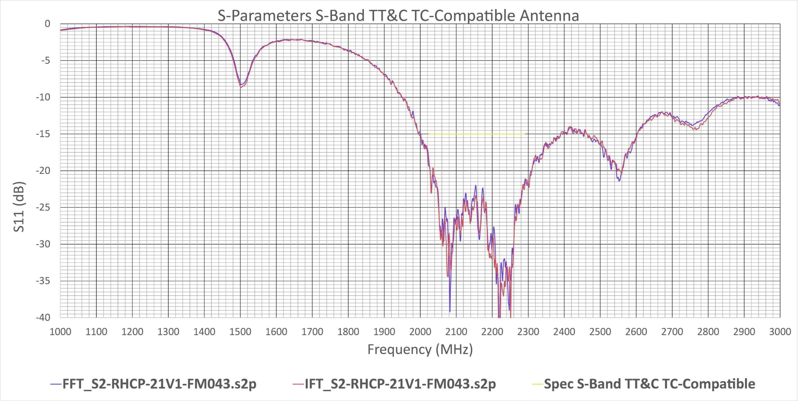
We conduct detailed measurements of the S-parameters and the radiation pattern to evaluate the antenna's RF functionality under various conditions: Initial S-parameter tests serve as a reference performance for all subsequent tests.
See more
2
Moist Heat Test:
To gauge resistance to moisture during ground storage prior to launch, the antennas are exposed to hot, humid conditions.
See more
3
Vibration Tests:
To simulate the vibration conditions during launch (acceleration, engine combustion instabilities, sound pressure on the fairing), our antennas undergo a vibration tests: quasi-static acceleration and random vibration tests to ensure structural integrity.
See more
4
Shock Tests:
These tests ensure that the antennas can withstand sudden and extreme forces, typically experienced during stage separation or appendices deployment in-orbit.
See more
5
Vacuum Thermal Cycling:
Mimicking the vacuum of space, this test evaluates the antenna's performance under extreme thermal cycles.
See more
6
Long Thermal Cycling:
Performing accelerated thermal testing, we ensure that the antenna can withstand the space environment throughout its entire lifetime with the expected performances.
See more
7
Power Handling Test:
This ensures the antenna can handle high power levels without performance degradation.
See more
8
RF Leakage Test:
If the antenna is equipped with a test cap, we perform a radio frequency leakage test to ensure no unintended emissions occur during the integration phase to protect the operator.
See more
9
Final Functional Test:
S-Parameters, radiation pattern measures and a final rigorous visual inspection are conducted to ensure every parameter meets our demanding standards.
See more
Close
Step 1Initial Functional Test:
Parameter S - Space Antenna

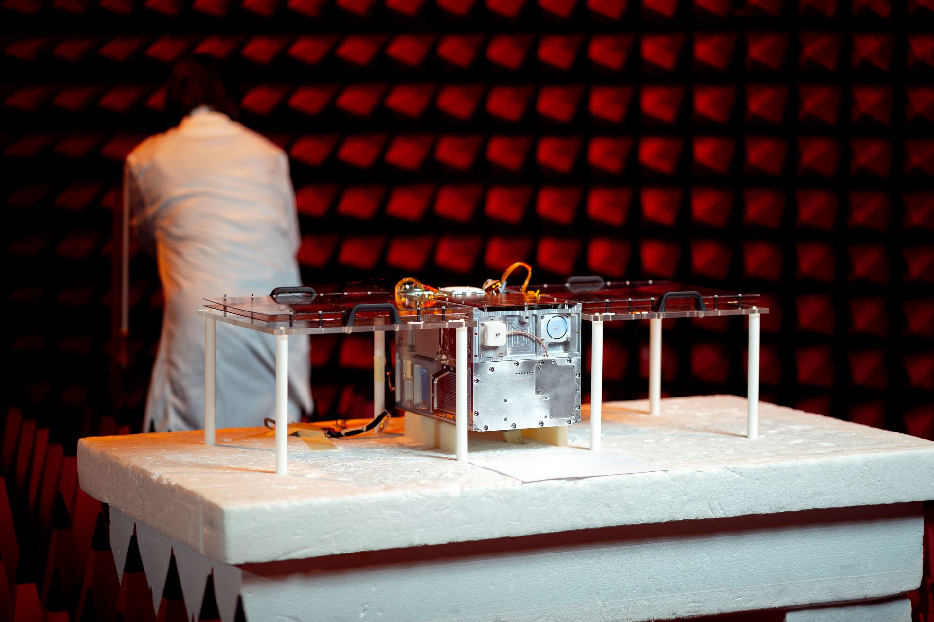
To guarantee optimal performance in space, we carry out intricate measurements of the radiation pattern and the S-parameters. By evaluating the antenna’s primary functionality under diverse conditions, we can confidently vouch for its operational consistency in various space environments.

In terms of testing resources, Anywaves relies on the following equipment:

  • Keysight N9918A FIELDFOX HANDHELD Microwave Analyzer: Vectorial Network Analyzer, 26.5 GHz max. frequency
  • Copper Mountain S5243 2-PORT 44 GHz Analyzer: Vectorial Network Analyzer, 44GHz max frequency.
  • MVG STARLAB-1B: Radiation pattern measurement system, from 800MHz to 18GHz

More information

Close
Step 2Moist Heat Test:
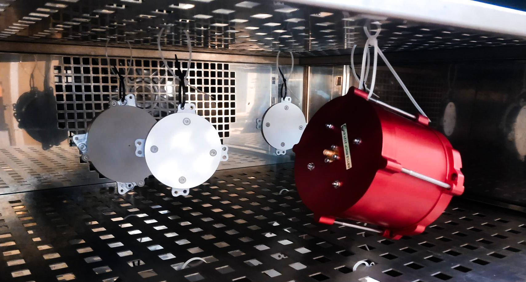
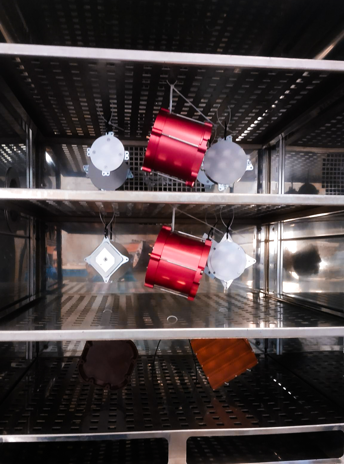
Thermal 01 Thermal 02 Thermal 03 Thermal 04

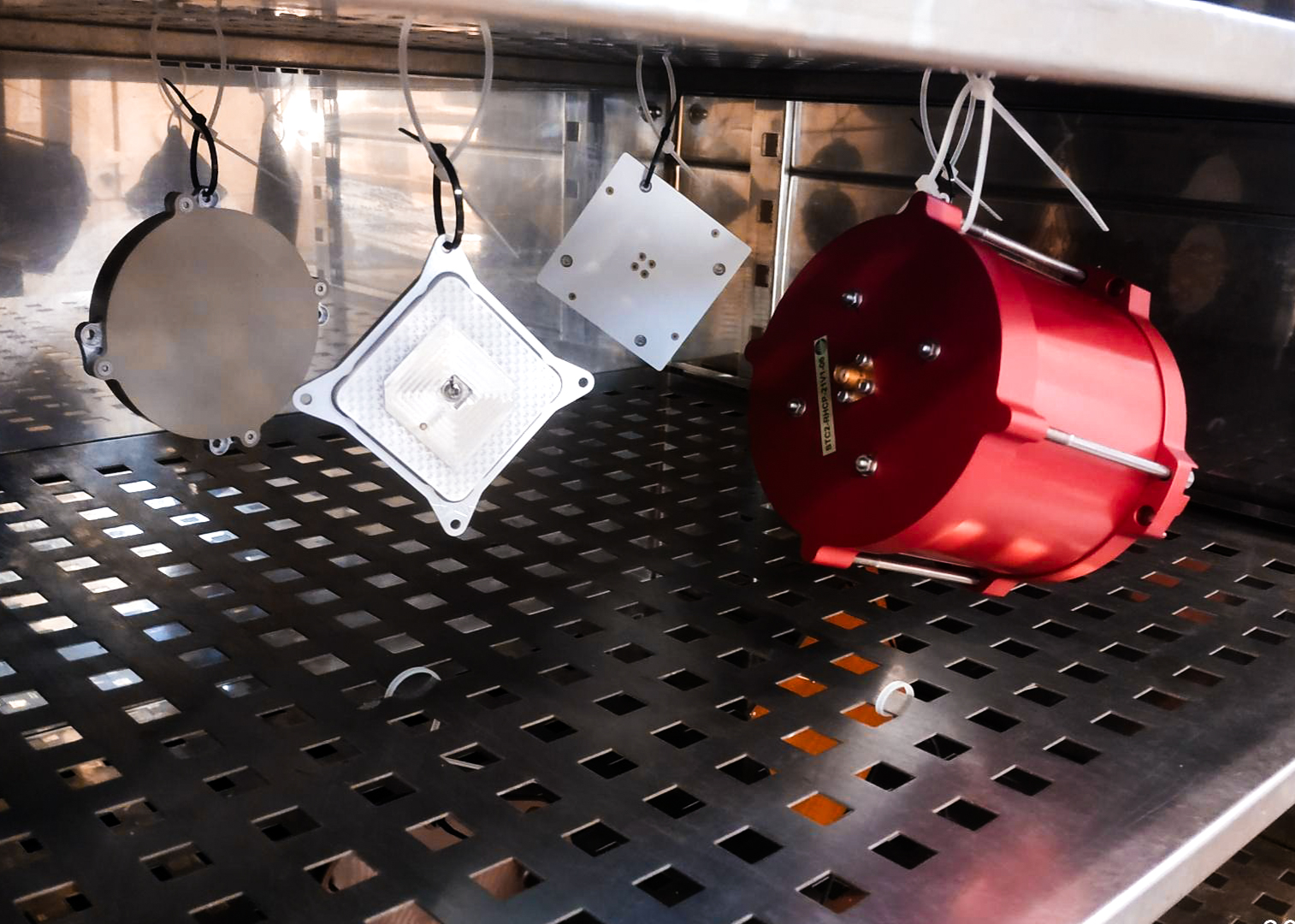
Recognizing the importance of moisture resistance during ground storage leading up to the launch, we subject our antennas to hot, humid conditions. This ensures that the antenna remains uncompromised and ready for deployment in the challenging space setting.

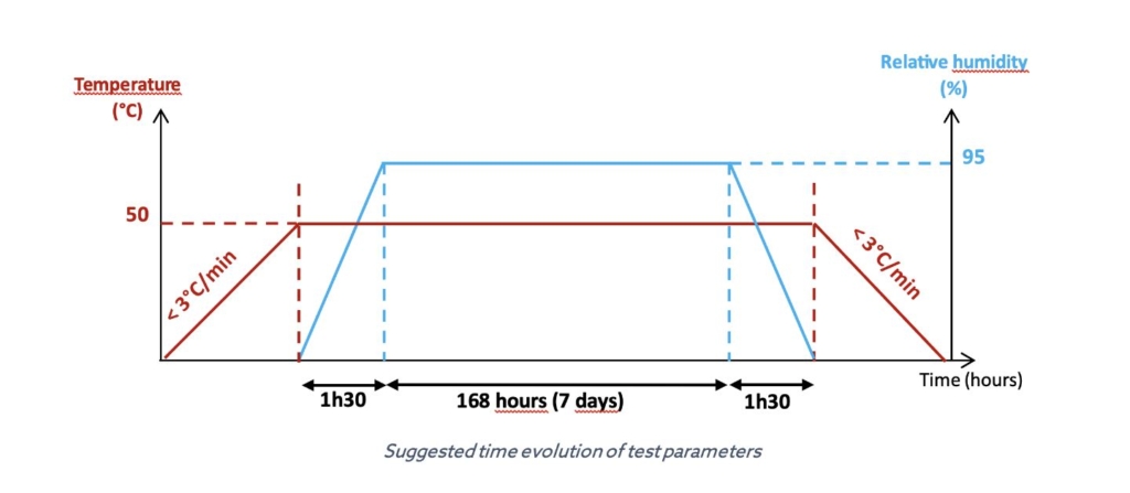
Tests conditions :

  • Stabilized moist heat test
  • Dwell temperature: 50°C ± 2°C
  • Relative Humidity: 95% ± 3%
  • Dwell time: 168 hours (7 days)
  • Temperature ramp: < 3°C/min
  • Relative Humidity ramp duration: 1h30 ± 1h00
  • No condensation

Moist Heat Test graph

Close
Step 3Vibration Tests:
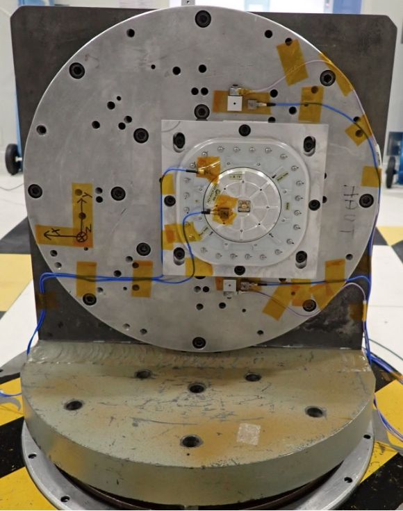
vibration power

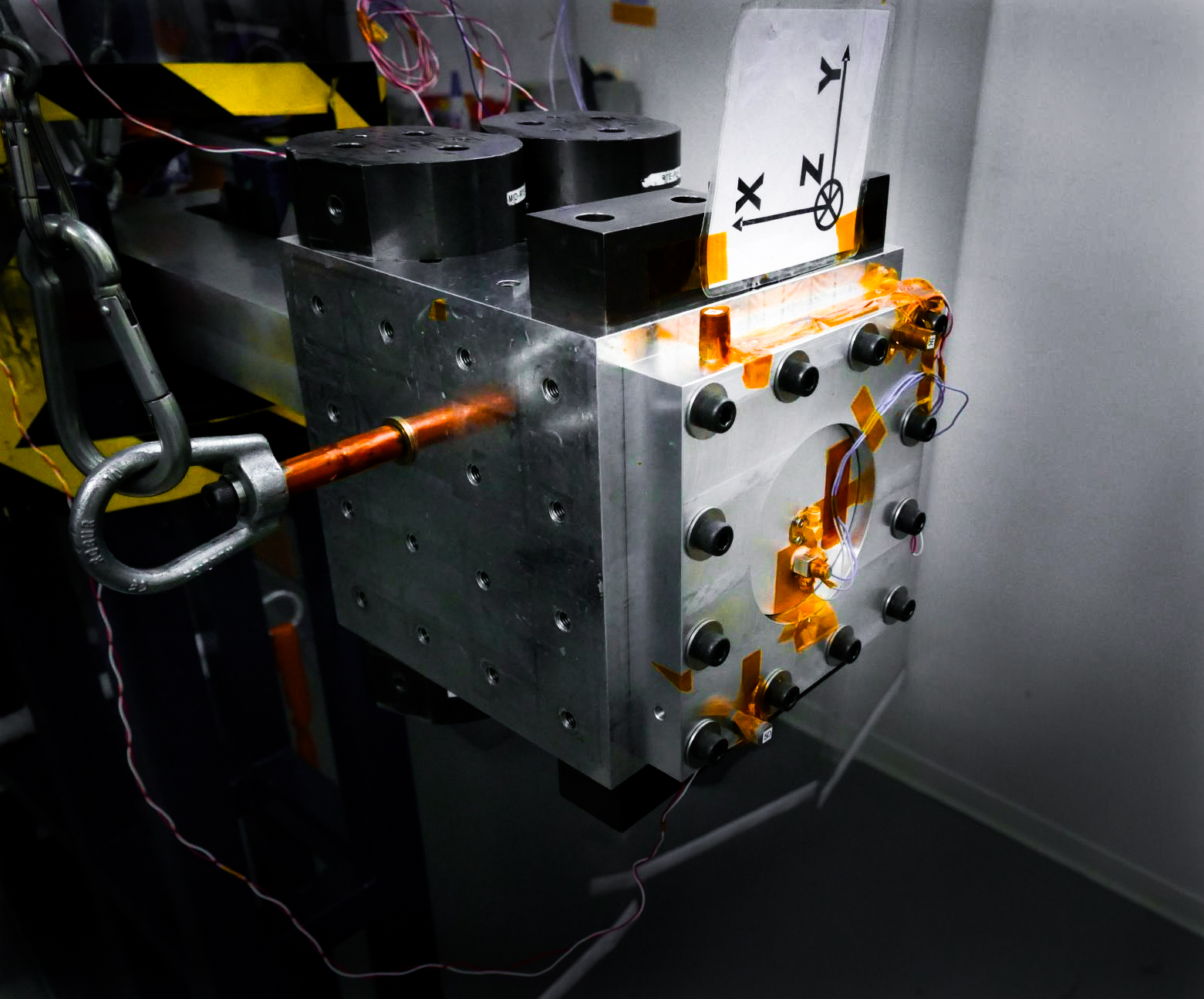
To authentically replicate the tumultuous conditions during launch, our antennas undergo rigorous vibration tests, including both quasi-static acceleration and random vibrations. This prepares them for real-world scenarios like engine combustion instabilities and sound pressure levels that induces random vibrations on the fairing’s payloads.

Tests conditions :

Quasi-static acceleration test :

  • Performed on 3 axis
Load50 g at 100 Hz
TypeQS
Duration3 seconds
  • Random vibration environment

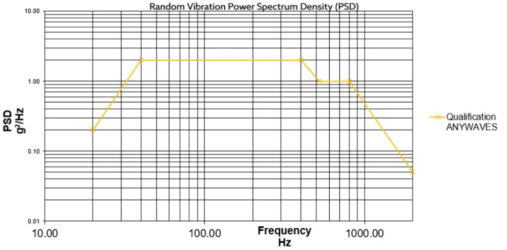
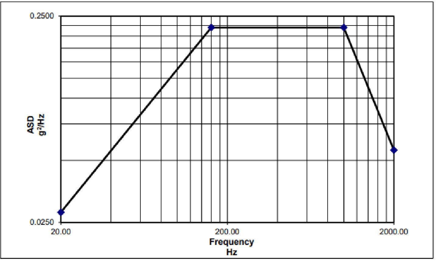
Our random vibration test is generally performed at ~40 gRMS for 120 seconds on 3 axis, with a high plateau from 100 Hz to 800 Hz.

A typical example is given below:

vibration power graph


Close
Step 4Shock Tests:
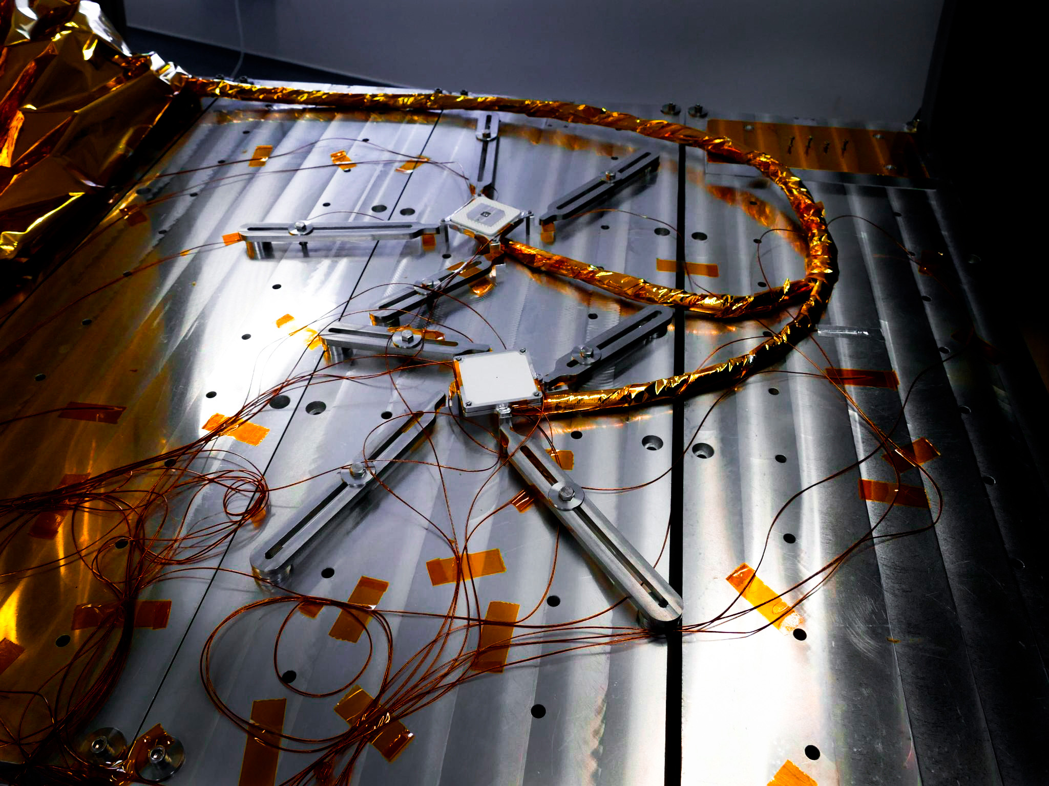
shock testing

Our shock tests are paramount to ensure that our antennas remain undamaged under the extreme forces encountered during processes like stage separation or appendices liberation while in orbit.

Tests conditions :

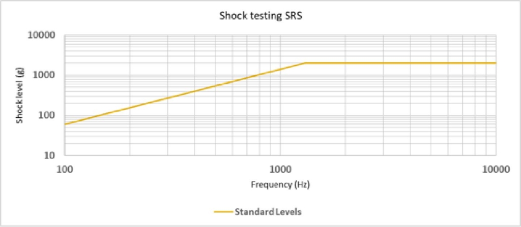
Shock testing is applied on 3 axis with the following testing conditions:

Duration/Qty3 axis, 3 times per axis
Loads100 Hz – 60 g
1300 Hz – 2000 g
10000 Hz – 2000 g

shock tests graph


Close
Step 5Vacuum Thermal Cycling:
Vacuum 01 Vacuum 02

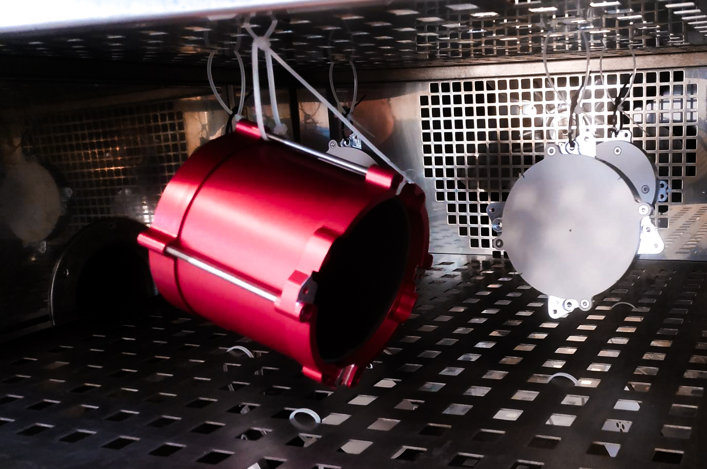
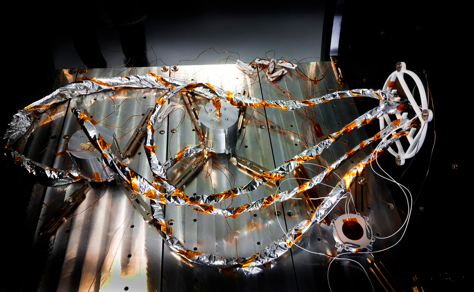
Space is an environment of extremes. By replicating the vacuum conditions of space, this test ensures the antenna’s consistent performance across varying thermal cycles, ensuring reliability when it matters most.

Tests conditions :

Temperature range-120°C / + 120°C
Temperature toleranceHot case 0°C/+4°C, Cold case -4°C/0°C
Number of cycles8
Stabilization dwell time2 hours
Vacuum level0,0013 Pa (1E-05 torr)
Temperature rate 1 < X < 2°C/min
RF monitoringContinuous

Continuing monitoring of the S-parameter of the antenna and its Test-Cap are done during the thermal cycling.

Close
Step 6Long Thermal Cycling:

By conducting accelerated thermal testing, we can vouch for the antenna’s ability to endure the rigorous space environment throughout its entire operational lifetime without compromising on its expected performances.

Tests conditions :

The recurring temperature fluctuations can induce thermal fatigue, ultimately culminating in product failure after numerous thermal cycles. To conduct accelerated life testing, the product can be subjected to cycles of elevated and reduced temperatures that surpass its typical operating temperature range. The thermal cycling testing parameters depend on mission lifetime and thermal conditions on-orbit. These are calculated based on Norris-Landzberg & Arrhenius models and thermal simulations. Typical testing parameters are given below.

Temperature range-55/+115°C
Temperature toleranceHot case 0°C/+5°C

Cold case -5°C/0°C

Number of cycles540
Stabilization dwell time10 min
Temperature rate10°C / min
Continuous RF monitoringNot mandatory
Close
Step 7Power Handling Test:
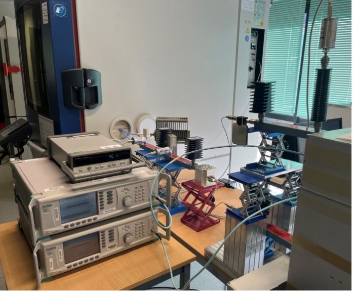
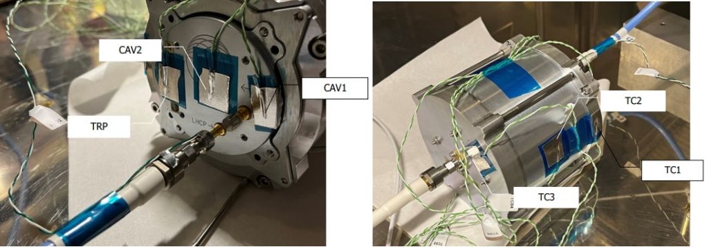
power handling

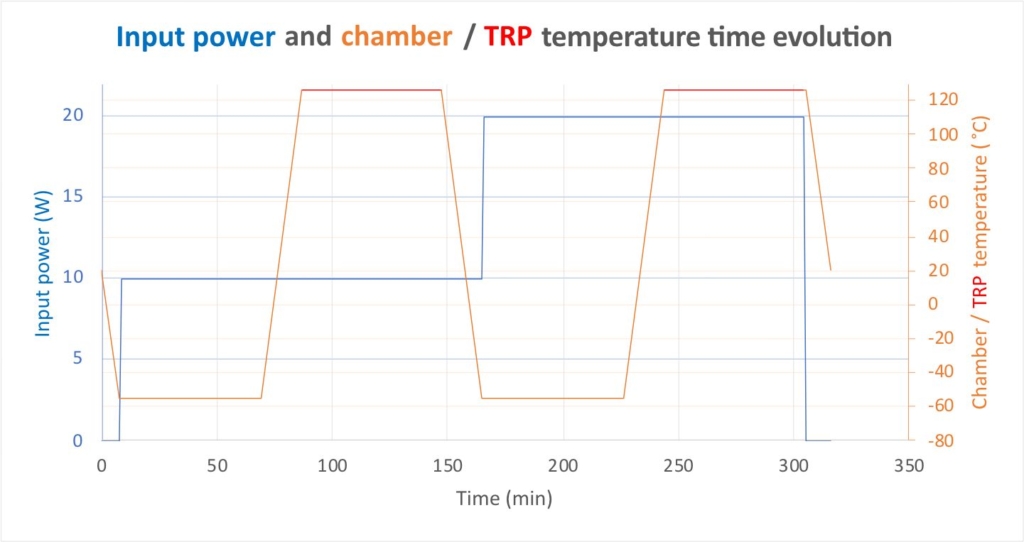
With high power levels being a constant for transmitting antenna during space operations, this test certifies that the antenna maintains optimal performance without degradation, even when handling escalated power levels.

Typical testing conditions :

Test typeRF power handling (thermal)
Maximum power20 W
Power tolerance[+0; +1] W
Duty cycleCW (Continuous Wave)
Input signal frequencyCentral frequency of the antenna
Minimum chamber temperatureTypically -55°C
Maximum TRP temperatureTypically +120°C
Temperature tolerance[-5;-0]°C / [+0; +5] °C
Thermal chamber temperature rate< 10 °C / min
PressureAmbient
Dwell time1 hour
RF monitoringContinuous

power handling test power handling 2

Close
Step 8RF Leakage Test:

When equipped with a test cap, our team conducts a meticulous radio frequency leakage test. This assures that the antenna remains faultless and no unintended emissions, potentially harmful in space missions, occur.

Tests conditions :

For emission’s antennas, RF leakage are measured in order to be sure that the operators are safe when the entire RF chain is tested through the Test-Cap. The aim of this test is to be sure that the RF leakage is below the recommendation on the limitation of exposure of the general public to electromagnetic fields (0 Hz to 300 GHz) [1999-519-CE] to ensure the safety of our customers.

Close
Step 9Final Functional Test:
Parameter S - Space Antenna

Our commitment to quality culminates in this step. A thorough visual and functional examination ensures that every aspect of the antenna aligns with our stringent standards, promising unparalleled performance in space.

We also perform another measurement of the parameters S to be sure that the results are conformed to the ones obtained during the Initial Functional Test.

Acceptance Tests

According to the ECSS, the acceptance tests are way lighter than the qualifications tests. They ensure that there were no problems during the assembly of the antenna and that its integrity wasn’t compromised.

1
S-parameter Test:
Initial S-parameter tests serve as a baseline for all subsequent tests.
See more
2
Random Vibration Test:
To simulate launch conditions and ensure structural robustness.
See more
3
Thermal Cycling:
A thermal cycle ensures the antennas can withstand temperature fluctuations.
See more
4
Final S-parameter and Visual Inspection:
To validate that the antennas meet all functional and visual specifications.
See more
Close
Step 1S-parameter Test:
Parameter S - Space Antenna

To guarantee optimal performance in space, we carry out intricate measurements of the the S-parameters. By evaluating the antenna’s primary functionality under diverse conditions, we can confidently vouch for its operational consistency in various space environments.

Tests conditions :

In terms of testing resources, ANYWAVES relies on the following equipment:

  • Keysight N9918A FIELDFOX HANDHELD Microwave Analyzer: Vectorial Network Analyzer, 26.5 GHz max. frequency
  • Copper Mountain S5243 2-PORT 44 GHz Analyzer: Vectorial Network Analyzer, 44GHz max frequency.


Close
Step 2Random Vibration Test:
random vibration test

To authentically replicate the tumultuous conditions during launch, our antennas undergo rigorous vibration tests. This prepares them for real-world scenarios like engine combustion instabilities and sound pressure levels that induces random vibrations on the fairing’s payloads. It also allows to check the mechanical integrity of each flight model.

Tests conditions :

Acceptance random vibration only is performed on 1-axis at 17,7 gRMS for 60 seconds. For Qualification tests conditions, please refer to the dedicated section.

Close
Step 3Thermal Cycling:
thermal cycling

Verifying the antenna’s resilience against temperature fluctuations in space, we conduct a controlled thermal cycle.

Tests conditions :

Unlike qualification thermal cycling test, the acceptance test version is performed at ambient conditions:

Temperature range-40°C /+75°C
Temperature toleranceHot case  0°C /+3°C, Cold case  -3°C /+0°C
Number of cycles4
Stabilization dwell time15 min
Temperature rate 2°C / min
RF monitoringAfter testing


Close
Step 4Final S-parameter and Visual Inspection:
Parameter S - Space Antenna

As a commitment to delivering only the best, each antenna undergoes a thorough final inspection, ensuring it aligns with both functional and visual benchmarks before deployment.

To do so, we carry out measurements of the S-parameters to be sure that the results match the ones obtained during the Initial Functional Test. We also perform a visual inspection and check that the packaging is faultless and ready to be delivered.

Why trusting us for your Antenna Testing?

01 number test

Number of Tests

Our testing process includes more tests than the industry average, increasing confidence in product reliability.

02 quality

Quality and Rigor

We delve deeper into each test, applying a rigorous methodology to uncover even the most elusive issues.

03 test tracability

Test Traceability

Every qualification test is meticulously recorded, and each acceptance test is detailed in a report included in the EIDP, offering unmatched transparency and traceability.

04 report

Reports automated with Connektica

Thanks to our partnership with Connektica, Anywaves can provide automated generated report for each flight model.
This report includes pictures and results of each test performed and it will be delivered alongside the antenna.

a lean inspired

A Lean-Inspired Industrialization Process

We’ve infused lean manufacturing principles into our rigorous testing process, ensuring both efficiency and precision. Our meticulous and standardized testing protocols, paired with automated reporting, ensure that every antenna we produce undergoes consistent, uniform, and detailed evaluations.
This lean-inspired approach not only guarantees the reliability and quality of each antenna but is also optimized for high-volume industrialization, ensuring every product meets our exacting standards regardless of order size.

Custom Testing Solutions

Recognizing the ever-evolving challenges and requirements of space missions, Anywaves offers additional or specific tests upon request. We have partnerships with top-notch testing facilities and specialists, making us capable of performing any type of test you may need.
Whether it’s a unique environmental condition or a specific functional criterion, our network and expertise ensure that your unique testing requirements will be thoroughly addressed.
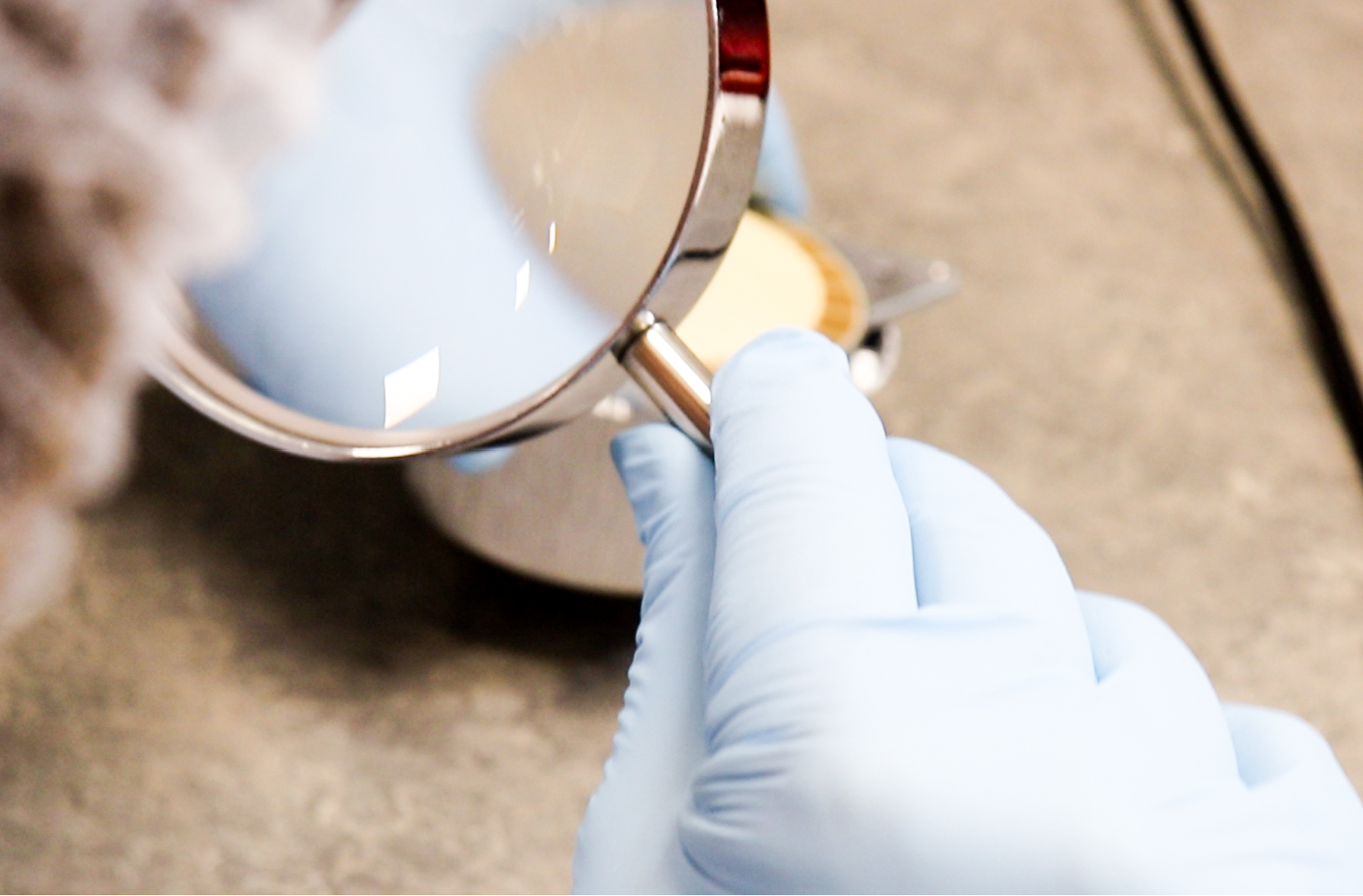
Custom testing solutions
OUR AREA OF EXPERTISE
1/4

Design

We understand that excellence in space antenna technology hinges not just on innovation but also on rigorous, finely-tuned design processes. Our comprehensive approach to spatial project management ensures that every antenna we create is ready to meet the extreme challenges posed by the space environment while maximizing performance and reliability.

Innovation

Anywaves’ Technical Projects team utilizes cutting-edge concepts to design compact yet high-performance antennas for the Space market. Our antennas undergo a rigorous process from concept creation to qualification, always with a practical innovation perspective. We combine flight-proven expertise in materials and quality to lead the future of space communication.

Industrialization

Industrialization is not an afterthought; it’s an integral part of our mission to provide high-quality, reliable space antennas. By emphasizing a seamless transition from R&D to mass production, we ensure that our innovative designs can be scaled efficiently, reliably, and economically.

Manufacturing

We recognize that a great design is only as good as its manufacturing. That’s why we’ve invested in cutting-edge technology and processes to ensure that our space antennas are not only innovative but also reliably and efficiently produced.

Quality Management

We believe that quality is an intricate weave of meticulous planning, cutting-edge technology, and relentless dedication. This tapestry is not just about meeting standards; it’s about setting them. Our Quality Management Process ensures that each space antenna we create is flawless so it can deliver optimum performance.

design color
Quality control worker analyzing scientific experiment on a manufacturing machine.
Indus
manufacturing space antennas
Quality

How Can We Help?

We look forward to hearing from you