There is a good chance you have already owned a low-noise block downconverter, or LNB, without ever thinking about it: it is the small metal cylinder sitting at the focus of a satellite TV dish. It looks unremarkable. But it occupies the one position in a receive chain where a design mistake is almost impossible to fix later — which is reason enough to understand it properly, wherever it is used.
An LNB does two jobs:
- It amplifies a very weak incoming signal, adding as little noise of its own as possible.
- It shifts that signal down to a lower frequency — one the rest of the chain can carry, filter and digitise far more easily.
A satellite payload needs exactly those two jobs done, just behind the antenna instead of behind a dish on a roof. This article looks at how an LNB actually performs them, and at what changes when the unit has to work in orbit rather than on a roof. A second article in this series covers how to choose one for a specific mission.
LNA or LNB? The terminology matters
The two terms get used interchangeably. They shouldn’t be.
A low-noise amplifier (LNA) does one thing: it provides low-noise gain. A low-noise block downconverter (LNB) does that and frequency conversion. Inside it, a mixer — driven by a local-oscillator (LO) signal — shifts the amplified signal down to a lower intermediate frequency (IF). That LO signal can be generated inside the unit or supplied to it from outside; both are still LNBs.
The word “block” refers to a contiguous chunk of bandwidth being translated together, not a single channel being tuned. It doesn’t mean the entire frequency range a unit covers gets converted all at once — the next section shows why that distinction matters.
The short version: every LNB contains an LNA. Not every LNA is part of an LNB.
Job one: amplify without adding noise
Here is the key idea, before any equation: in a receive chain, the very first amplifier sets the noise floor for everything that comes after it. Whatever noise that first stage adds is essentially locked in — no downstream component can remove it.
This isn’t a rule of thumb. It follows from an equation Harald T. Friis published in 1944, still the standard reference for cascaded noise figure:
F(total) = F₁ + (F₂ − 1)/G₁ + (F₃ − 1)/(G₁·G₂) + …
F is noise factor and G is gain, both expressed as plain ratios rather than decibels (datasheet values in dB need to be converted first). Read plainly, the equation says: the noise contributed by each stage gets divided down by the gain of every stage before it. A high-gain, low-noise first stage buries the noise of everything downstream.
The practical consequence: any passive loss placed before that first gain stage — a cable, a connector, a filter — attenuates the signal while there’s no gain yet available to dilute what comes after. A passive component at room temperature adds noise equal to its own insertion loss, decibel for decibel.
What half a decibel actually costs
Decibels are abstract until you convert them into kelvin. Space engineers usually do this conversion, because noise temperatures add up directly at a shared reference point (antenna, feed, receiver), whereas decibels don’t:
Te = 290 × (10^(NF/10) − 1)
Take an LNB with a 1.2 dB noise figure — a realistic value for a space-qualified unit. Its equivalent noise temperature is about 92 K.
Now add half a decibel of cable and connector loss in front of it, at room temperature. That loss alone contributes roughly 35 K, and — because it sits ahead of any gain — nothing downstream can compensate for it. Work through the full cascade and the receiver noise temperature comes out at about 139 K: equivalent to a 1.7 dB noise figure.
Half a decibel of avoidable loss ahead of the amplifier raises receiver noise temperature by roughly 51% — from 92 K to 139 K. No amount of downstream processing recovers it.
How much that costs at system level depends on what the antenna is looking at. Pointed at cold sky, the antenna itself sees only tens of kelvin, so the receiver dominates the total noise budget and that increase matters a great deal. Pointed at Earth, the antenna sees something closer to 290 K, and the same increase is proportionally smaller. It is never free — but its weight in the budget depends on the mission.
The design rule that follows is simple: minimise insertion loss between the antenna output and the first low-noise gain stage. This doesn’t mean no passive components can sit ahead of the amplifier — an orthomode transducer, a polariser, a coupler, a preselect filter all legitimately can — only that their loss has to be deliberate and accounted for in the noise budget.
At system level, this all collapses into a single figure of merit: G/T, the receive antenna gain divided by the total system noise temperature. Lowering receiver noise temperature raises G/T, which raises link margin. That margin can sometimes be traded elsewhere in the design — a smaller antenna, less transmit power at the other end — though those trade-offs aren’t strictly interchangeable, since each has its own consequences for coverage, regulation, cost and interference. (Qorvo’s review of satellite link budget analysis walks through this in more depth.)
Job two: move the signal down in frequency
The second job relies on a principle radio engineering has used for over a century: heterodyning. In simple terms, two signals — the incoming RF signal and the local oscillator — are combined in a component called a mixer. The result contains new frequency components at the sum and the difference of the two input frequencies. A filter then keeps the one you want: for a downconverter, that’s the difference, which is lower and easier to work with. (ScienceDirect’s overview of heterodyne receivers covers the underlying theory.)
A real mixer is messier than that description. Alongside the wanted output, it also produces LO-to-RF and LO-to-IF leakage, harmonics, and a family of other unwanted combinations. Careful frequency planning and filtering exist specifically to keep those from landing inside the wanted IF band.
Why go to this trouble? Because working at high frequency is expensive: cables lose more signal, filters are harder to build, and analogue-to-digital converters can’t sample arbitrarily fast. Translating the signal down to a lower IF makes everything downstream cheaper, lighter and lower-loss — which is exactly why this conversion happens right at the antenna, before the signal has to travel any distance along the RF chain.
When the LO is supplied externally rather than generated inside the unit, it brings its own consequences: its frequency accuracy maps directly into IF frequency accuracy, and its phase noise can degrade the signal or, near a strong nearby interferer, add extra in-band noise through a mechanism called reciprocal mixing. An external LO turns what would otherwise be an internal design detail into a system-level requirement.
The image frequency — and why it can’t be fixed afterwards
Frequency translation has a catch. For any given LO frequency, two different input frequencies produce the same difference frequency: the signal you want, and a mirror-image signal on the other side of the LO. In a conventional design, both land on top of each other at the same IF output.
The irreversible part is that collapse into a single IF signal — not the mixing step itself. Once the two are merged, ordinary filtering can’t tell them apart. The unwanted one has to be dealt with before that merge happens: through filtering ahead of the mixer, a specialised image-reject mixer, or an architecture that keeps the signal in a two-part (quadrature, or “I/Q”) form long enough to cancel out the unwanted side coherently. It’s worth noting that even without a specific interfering signal in that image band, thermal noise naturally sitting there folds into the IF the same way, quietly raising the noise floor if it isn’t rejected.
Spectral inversion
There’s a second, related quirk in how mixing works, and it catches people off guard the first time they meet it. The LO can sit below the wanted signal’s frequency (low-side injection) or above it (high-side injection), and the two give opposite results:
- Low-side injection: f(IF) = f(RF) − f(LO) → frequency order is preserved
- High-side injection: f(IF) = f(LO) − f(RF) → frequency order is inverted
With low-side injection, the translated band comes out the right way round. With high-side injection, the band comes out mirrored: what was at the bottom of the input band ends up at the top of the IF band, and vice versa.
Nothing is lost — the information is all still there — but the receiver has to know which case applies. Told in advance, a digital receiver corrects for it easily. If the frequency plan and the receiver disagree about it, channel mapping or demodulation fails.
A familiar example — up to a point
Consumer satellite TV shows this architecture at its most familiar. A universal Ku-band LNB covers roughly 10.7–12.75 GHz — but not in a single step. That span is wider than the L-band IF range it feeds into, so the unit switches between two LO frequencies, each translating one part of the RF band into an overlapping portion of the same 950–2150 MHz range that ordinary coaxial cable carries indoors. (ScienceDirect’s overview of low-noise block downconverters covers this in more detail.) Even the most mass-produced LNB in the world segments its coverage rather than converting everything at once.
The comparison stops there, though. A consumer unit is built in huge volume for one well-defined application, and never has to survive vacuum, radiation or a decade of thermal cycling. A noise-figure number quoted for a rooftop unit is rarely comparable to one quoted for a space-grade unit without first checking that frequency, bandwidth, temperature and the statistical basis of the number — typical versus guaranteed — actually match.
Inside a space-grade LNB
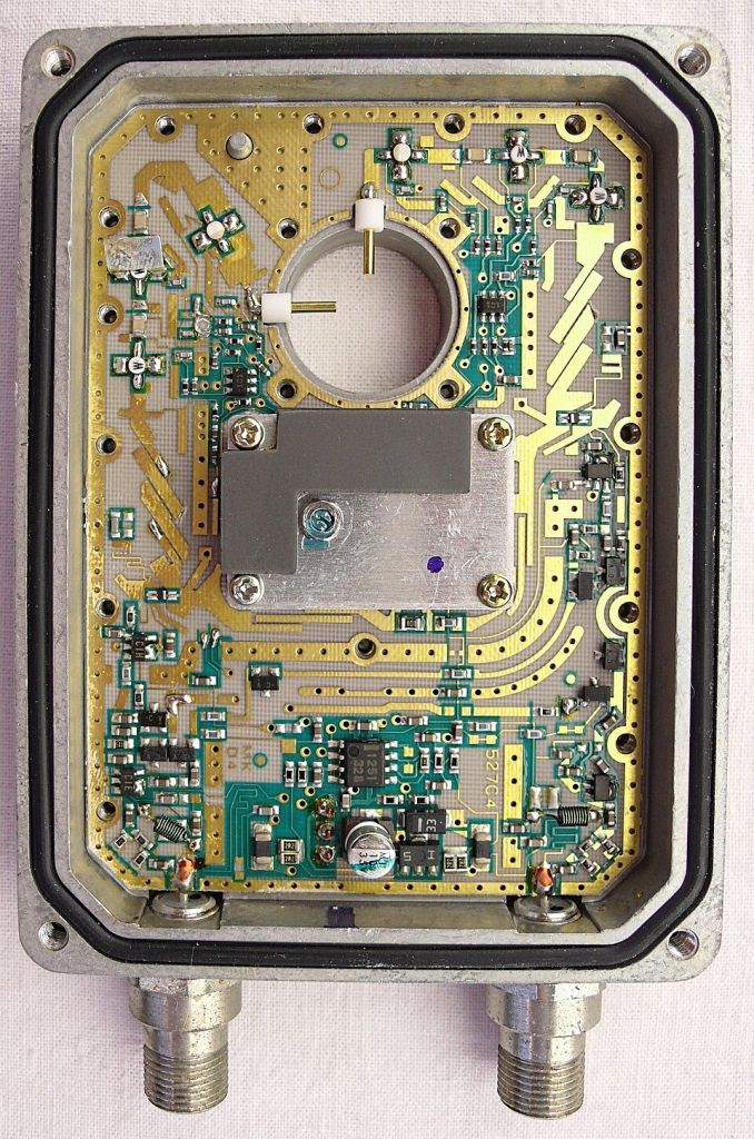
Functionally, a space-grade LNB does the same RF job as the one on a roof — it’s simply built to survive a much harder environment. The signal path itself is the same short chain either way: it enters from the antenna port, passes through the low-noise amplifier and a filtering stage, and reaches a mixer, where the local oscillator translates it down to the IF output. What changes — thermal design, materials, component selection, interfaces, manufacturing controls, verification — is driven entirely by the mission environment, covered in the next section.
Many multi-channel LNBs run two or more parallel RF-to-IF paths from a single, shared LO. Because every channel draws from the same source, LO frequency error and phase noise are largely common to all of them — sharing the LO removes the independent drift that two separate oscillators would introduce. What it doesn’t guarantee, on its own, is that the channels stay matched in phase: distribution paths, the mixers themselves, filters, cable runs and temperature all add their own channel-to-channel differences. Wherever tight matching matters, the full relationship between channels has to be measured across frequency and temperature — not assumed from the shared LO alone.
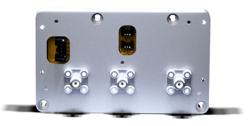
Polarisation is where this becomes concrete. A dual-polarisation antenna outputs two orthogonal linear signals, often labelled H and V. These can be combined into left-hand or right-hand circular polarisation (LHCP/RHCP) using a 90-degree (quadrature) hybrid — a component that combines the two signals at equal strength with a ±90° phase offset. When this combination happens before amplification and down-conversion, it’s the antenna and hybrid’s own amplitude and phase balance that sets the achievable circular-polarisation purity — the axial ratio and cross-polar discrimination covered in our guide to antenna polarisation. The down-conversion channels still need to stay well matched with each other, since any mismatch feeds into calibration — but the polarisation purity itself is set upstream, at the hybrid. Get that balance wrong and polarisation purity degrades, even though the signal level itself looks perfectly normal. (The Anywaves LNB, for example, offers an optional hybrid module ahead of its dual-channel architecture.)
What “space-grade” actually changes
“Space-grade” isn’t a single label stamped on a component — it’s a mission-specific combination of design rules, materials, parts assurance, manufacturing processes, margins and verification evidence. And it touches an LNB’s RF performance far more directly than the phrase suggests.
Thermal design in a vacuum.
On a rooftop, a warm component sheds heat into the surrounding air by convection. In vacuum, that option simply doesn’t exist: heat generated inside the unit can only leave through conduction into the housing and mounting interface, and ultimately through radiation to the spacecraft’s thermal-control system. For an LNB dissipating several watts, how well that thermal path is designed affects junction temperature directly — and junction temperature feeds straight back into noise figure, gain, filter loss, and phase and group-delay stability. Thermal design is as much an RF performance parameter as a mechanical one.
Outgassing and contamination control.
Materials that behave perfectly well in air can release volatile compounds in vacuum, which then condense on colder surfaces elsewhere on the spacecraft — optics, radiators, sensors. On ECSS-governed projects, materials and processes are selected within a mission-specific contamination-control programme (ECSS-Q-ST-70-02C defines the outgassing test used to screen candidate materials). In practice, this rules out a good deal of standard commercial adhesives, coatings, cable jackets and lubricants.
Radiation.
Radiation effects on electronics generally fall into three categories. Total Ionizing Dose (TID) builds up gradually over the mission, shifting semiconductor parameters, and is usually quoted in krad(Si). Displacement damage (also called Total Non-Ionizing Dose, or TNID) is a different mechanism, where energetic particles knock atoms out of place in the semiconductor lattice — its effect depends heavily on the specific technology involved. Single Event Effects (SEE) are probabilistic rather than cumulative: a single high-energy particle can upset, or in the worst case destroy, a device at any point in the mission. Guarding against all three is an ongoing process — defining the radiation environment, analysing dose and SEE risk, selecting parts accordingly, and applying margins, shielding or circuit-level mitigation where needed (per ECSS-Q-ST-60-15C Rev.1 (2025), and, for total-dose testing specifically, MIL-STD-883 Method 1019).
Thermal cycling.
Many low-Earth-orbit missions pass repeatedly between sunlight and eclipse — though exactly how often and how severely depends on altitude, orbital plane, beta angle and season; a satellite doesn’t necessarily eclipse on every orbit. Over a multi-year mission, this can still add up to thousands of thermal transitions, and both mechanical integrity (solder joints, connectors, material interfaces) and RF performance have to hold across the full qualified temperature range — not just at ambient.
Launch and parts assurance.
The unit also has to survive the mechanical loads of launch itself — vibration, shock, and the stresses on interfaces and connectors during ascent — verified through a qualification, protoflight or acceptance test campaign. And its electronic components are typically sourced and traced under a parts-assurance programme suited to the mission’s risk tolerance, rather than bought as standard commercial parts.
All of this is why a space-grade unit goes through a qualification and test campaign that a consumer part never sees. We cover what that involves in our overview of the Anywaves testing process, and the specific challenges of testing RF hardware in our article on RF EGSE for antennas and payloads.
Frequently Asked Questions
What is the difference between an LNA and an LNB?
A low-noise amplifier (LNA) provides low-noise gain only. A low-noise block downconverter (LNB) combines that gain with frequency conversion, via a mixer driven by a local-oscillator signal that can be generated internally or supplied externally. Its output is already downconverted to a lower intermediate frequency. Every LNB contains an LNA; not every LNA is part of an LNB.
Why does the LNB have to sit close to the antenna?
Because the first gain stage dominates the noise performance of the whole chain (Friis, 1944). For a passive element at the standard reference temperature of 290 K, its noise figure equals its insertion loss, decibel for decibel. Either way, loss placed ahead of the first gain stage can’t be recovered downstream. Passive elements such as a polariser or a polarisation-combining hybrid can legitimately sit ahead of the LNB, provided their loss is accounted for in the budget.
How do I convert a noise figure into a noise temperature?
Te = 290 × (10^(NF/10) − 1), in kelvin, for the standard 290 K reference. As reference points: 0.5 dB corresponds to about 35 K, 1 dB to about 75 K, and 3 dB to 290 K. Noise temperatures are often preferred in satellite work because they add up directly at a shared reference plane, whereas decibels don’t.
What is the image frequency?
For a given local oscillator frequency, two different input frequencies produce the same difference frequency: the wanted signal and its mirror image on the other side of the LO. In a conventional design, both arrive at the same IF and can’t be separated by filtering afterwards — so the unwanted one has to be rejected before the two merge, whether through preselection filtering, an image-reject mixer, or an I/Q architecture.
What is spectral inversion, and when does it happen?
Spectral inversion is when a downconverted band comes out mirrored, with low frequencies mapped to high and vice versa. With low-side LO injection, f(IF) = f(RF) − f(LO) and the frequency order is preserved. With high-side injection, f(IF) = f(LO) − f(RF) and the order inverts. A receiver can correct for it, provided the frequency plan tells it which case applies.
Can an LNB support circular polarisation?
Yes, in more than one way. An antenna that is natively circularly polarised delivers LHCP or RHCP straight to the LNB input. Alternatively, a dual-polarisation antenna’s two orthogonal linear ports can be combined into circular polarisation by a 90-degree (quadrature) hybrid ahead of a dual-channel LNB.
Conclusion
Go back to that dish on the roof for a second. The small cylinder at its focus is doing exactly what its counterpart does behind a satellite antenna: catching a signal too faint to matter yet, and making sure nothing between the antenna and the rest of the chain adds noise it can never get back. The rooftop version does that once, for one band, built by the million. A payload LNB does it across a wider range, in vacuum, through radiation, launch loads and years of thermal cycling — with no one able to walk up and adjust it once it’s flying.
That’s really the argument for taking this component seriously: it’s the one part of the chain where a mistake made on the ground is still a mistake once the satellite is in orbit.
The second article in this series turns that into a decision: how to choose an LNB for a satellite payload — the frequency plan, the noise and gain budget, dual-channel behaviour, integration constraints, and the evidence worth asking a supplier for. In the meantime, you can look through our low-noise RF electronics and the wider payload electronics portfolio, or get in touch to talk through your front-end requirements.
Further reading
- H. T. Friis, “Noise Figures of Radio Receivers,” Proceedings of the IRE, 1944 — the original cascaded noise-figure derivation.
- Marki Microwave — Noise Figure and Receiver Sensitivity Explained
- Qorvo — Designing Efficient Satellite Links: A Review of the Link Budget Analysis
- ScienceDirect — Low Noise Block (topic overview)
- ScienceDirect — Heterodyne Receiver (topic overview)
- ECSS-Q-ST-70-02C — thermal-vacuum outgassing test used to characterise and screen candidate space materials.
- ECSS-Q-ST-60-15C Rev.1 (2025) — Radiation hardness assurance for EEE components. MIL-STD-883, Method 1019, is commonly used specifically for total-dose testing; Single Event Effects testing typically draws on other references such as ASTM F1192 or JESD57.

