The environmental conditions of space are very different to those on Earth. Exposure to a vast vacuum, intense radiation and constant cycling through thermal extremes subjects spacecraft to unprecedented mechanical stress. Even before reaching these conditions, there is the tumultuous journey into space aboard a rocket travelling at tens of thousands of kilometres per hour, experiencing intense vibrations for minutes after launch.
All of this is to say: the components and payloads built down on Earth aren’t being prepared for a simple road trip.
Spacecraft are going up with increasingly complex functions and mission lifetimes. There is a fine line between a successful, operational spacecraft and expensive orbital debris, and that line is largely determined by realistic, rigorous testing. At Anywaves, we know that surviving space means proving it on the ground first.
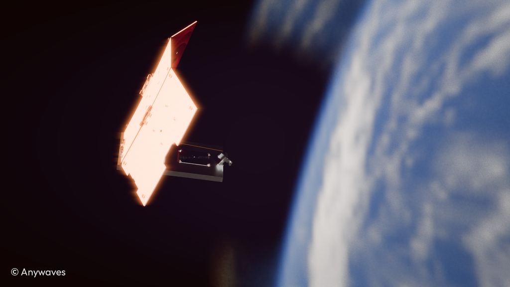
The Thermal Reality of Orbit
Components have a long journey ahead of them post-production, from storage to launch to finally reaching orbit. Although the biggest vibration test comes from powering through the atmosphere at velocities greater than 25,000 km per hour, the biggest source of temperature fluctuations throughout its lifetime occurs while orbiting. Spacecraft placed in LEO, MEO or GEO experience ranges from low cryogenic temperatures (-157°C) up to solar baking heat (121°C). The exact extremes depend on altitude, inclination and the Earth’s seasonal tilt.
A deep dive into orbital mechanics tells us spacecraft continuously cycle through three phases:
- Illumination: The ‘full sun’ configuration where solar radiation absorption peaks.
- Penumbra: The outer parts of the conical shadow cast by the Earth.
- Umbra: The central part of the shadow where all sunlight is excluded and temperatures plummet.
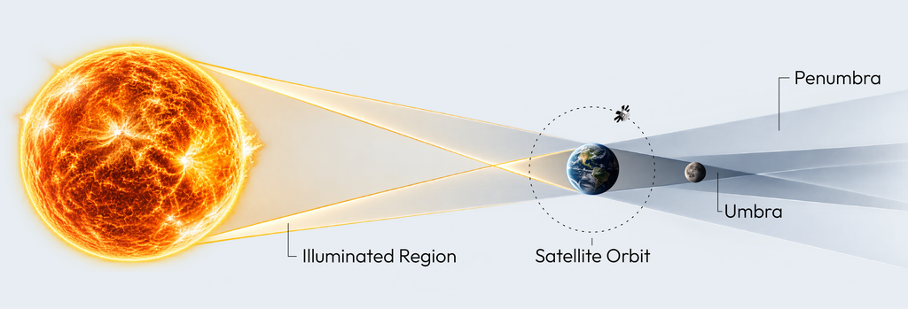
Note: Orbiting spacecraft are constantly receiving heat from Earth in two forms: Earth Albedo (solar radiation reflected off the planet’s surface) and Earth-emitted Infrared (the natural heat continuously radiated by the Earth itself).
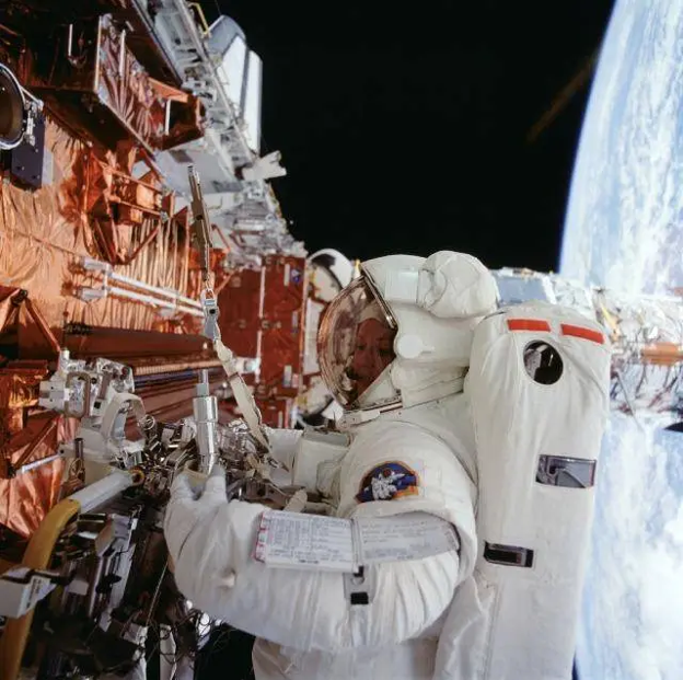
Did you know: The Hubble Telescope suffered from ‘thermal jitter’ caused by rapid temperature changes as it moved between illumination and umbra during each orbit. This was solved by Hubble’s first ever service mission where astronauts aboard the Space Shuttle Endeavour on the STS-61 mission in 1993 replaced the arrays with a redesigned second-generation set.
Generally, for circular orbits, lower altitudes mean more ‘shadow time’ for the spacecraft. However, each mission requires differently tailored orbits which can dramatically change the proportion of sunlight and shadow periods.
Because a component is made of different materials, those materials possess different Coefficients of Thermal Expansion (CTE). They deform at different rates, leading to internal stresses. These stresses can cause latent defects such as cracks and delamination, resulting in eventual component failure.
It is important to note how thermal stress impacts digital and RF components in fundamentally different ways. For standard digital electronics, the root cause of failure is typically CTE mismatch leading to mechanical breakage: cracked solder joints, severed wires or delaminated boards. However, RF thermal failures are a physics problem. In RF engineering, geometry equals performance. Electromagnetic waves are incredibly sensitive to the precise physical dimensions of the hardware carrying them. When extreme temperatures cause an antenna or filter to physically expand or warp, its electrical properties change. The hardware might remain mechanically intact, but its resonant frequency and circuit properties can drift completely out of alignment with the payload’s strict requirements.
What is Thermal Cycling?
Thermal cycling is the repeated cycling of temperatures between specified high and low extremes, subjecting materials and components to simulated mission conditions. During the test cycle, performance is monitored to verify successful functionality at the temperature limits, and throughout the transitions.
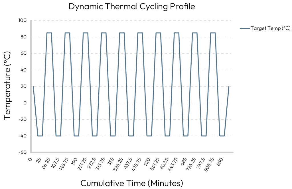
To understand the process, we have to define the key test parameters:
- Minimum/Maximum temperature: The absolute lowest and highest limits the assembled product can be exposed to. Crucially, this cannot exceed the ratings of the most sensitive individual part the subject is composed of.
- Ramp rate: The speed at which the applied temperature changes between the two extremes. Higher ramp rates provide better acceleration of fatigue, forcing hidden flaws to break efficiently, but not so fast that the subject breaks under catastrophic, unrealistic conditions.
- Dwell time: The time the subject is exposed to the extremes. It must be long enough for all external and internal components to reach thermal stability to test their maximum resistance to expansion and contraction.
- Number of Cycles: The total repetitions to determine fatigue resistance. Early failure detection typically uses 10-50 cycles, dramatically increasing for qualification testing.
- Failure rate: The frequency at which components break down due to cumulative thermo-mechanical stress.
Thermal cycling can be performed using several methods depending on the hardware and failure mechanism being investigated. Engineers execute this using three primary methods: Air-to-air (using controlled gaseous nitrogen environments at 1 atm to prevent oxidation), Liquid-to-liquid (rapid temperature transitions using liquid baths) and Thermal shock testing (extreme, instantaneous 100°C changes to identify vulnerable failure modes quickly). For space RF hardware, however, temperature alone does not reproduce the orbital environment. This is why qualification commonly goes a step further with thermal vacuum testing.
Taking it Further: Thermal Vacuum (TVAC) Cycling
A similar but alternative process is to carry out thermal cycling in an induced vacuum, replicating the conditions of space more exactly. While standard thermal cycling happens at atmospheric pressure, this process still exposes the component to repeating hot and cold temperatures between two extremes; however, it now takes place inside a high-vacuum chamber, with pressure levels typically below 10-4 Pa.

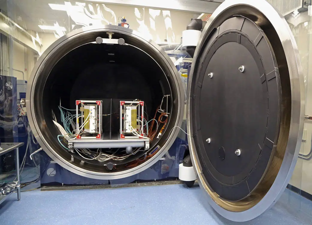
Since the air is removed, heat transfers solely through conduction and radiation, which accurately mimics orbital conditions. It also means that air can no longer act as a fan to the components, hence testing their own body heat management. TVAC proves that a piece of hardware’s thermal design, such as heat pipes and thermal straps, can actually keep the electronics from frying themselves when there is no longer air assisting them to cool down.
Beyond validating heat transfer, TVAC can specifically ensure components are protected against two distinct orbital hazards:
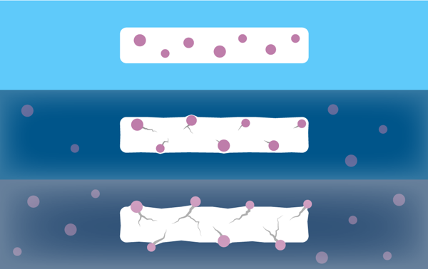
- Outgassing: A consequence of extreme low pressure causing normal plastics, glues and coatings to boil off trapped volatile molecules. TVAC helps catch these emissions on the ground before they condense on and ruin sensitive RF or optical surfaces in space.
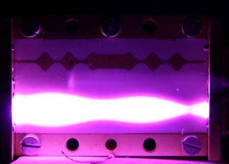
- Electrical Arcing: Electrical leaking, known as a corona discharge, spikes in a partial vacuum. Testing in this environment ensures high-voltage systems don’t short themselves and destroy the payload.
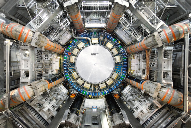
Did you know: It is impossible to create a perfect vacuum on Earth. However, one of Earth’s greatest marvels is the Large Hadron Collider (LHC) at CERN; classed as an Ultra-High Vacuum, it achieves pressures as low as 10⁻⁷ Pa throughout its 27 km pipes and even 10⁻⁹ Pa at particle collision points!
The Anywaves Advantage
According to industry norms, thermal cycling usually requires a minimum of 8 cycles, ensuring the last 3 are failure-free. However, the rise of satellite constellations demands more than just baseline compliance; it requires highly efficient, streamlined testing processes that deliver guaranteed reliability across high-volume production lines.
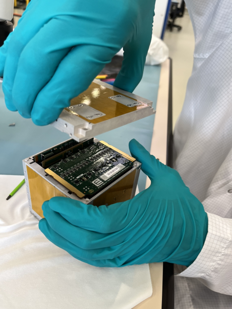
The merger of Anywaves with EmTroniX brings 34 years of combined experience in RF electronics and antenna manufacturing and testing processes. Now operating as a single global Space RF powerhouse, test sequences are specialised by product line across our two engineering hubs. Our Luxembourg site deals with highly complex electronics such as our printed circuit boards (PCBs) and SDRs, whereas our Toulouse site handles antennas, where physical geometry dictates electromagnetic performance.
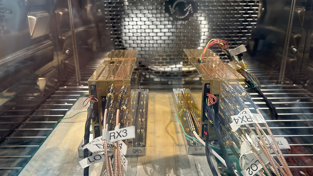
For Qualification Models, the thermal cycling portion of the test sequence for each site looks like:
| Thermal Cycling Stages | Luxembourg: RF & Payload Electronics | Toulouse: Space Antennas |
|---|---|---|
| Ambient Thermal Cycling | An atmospheric pressure test (-40°C to +85°C, 4°C/min ramp rate, 10-minute dwell time for 10 cycles) to demonstrate the individual components can function at temperature margins beyond predicted flight levels. | Takes place in Acceptance Testing. |
| TVAC Testing | Extremely low-pressure test (-30°C to +60°C, 0.75°C/min ramp rate, 1-hour dwell time for 7 cycles). | Extremely low-pressure test (-120°C to +120°C, 1 to 2°C/min ramp rate, 2-hour dwell time for 8 cycles). Continuous RF monitoring tracking the S-parameters of the antenna and its Test Hat. |
| Thermal Life Cycling (Life Test) | An extreme test designed to prove the design survives long-term thermo-mechanical fatigue over the full operational life. | To vouch for the antenna’s ability to endure the space environment throughout its entire operational lifetime but continuous RF monitoring is not mandatory. |
Tech Spotlight: The Anywaves Test Hat
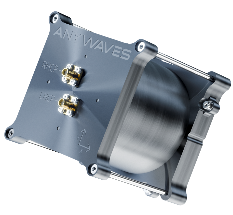
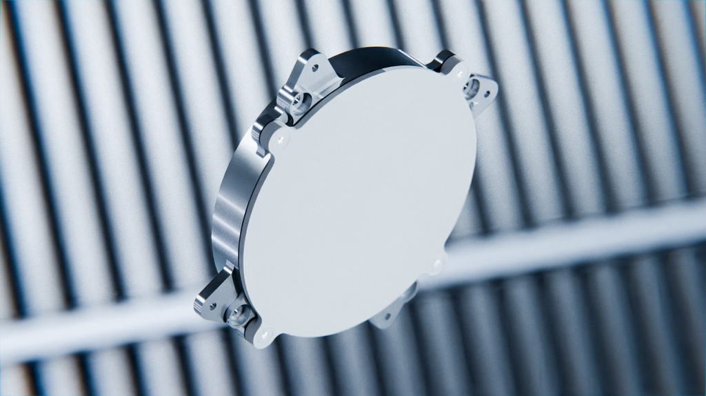
For an RF antenna, surviving the temperature excursion mechanically is only half of the qualification challenge. The antenna must also maintain its electromagnetic performance as its materials expand and contract. This creates a practical testing problem: how do you monitor RF behaviour while the antenna is sealed inside a thermal-vacuum chamber?
Anywaves addresses this with its Test Hat, a compact RF test fixture mounted directly over the antenna aperture. It enables RF measurements to be performed while the antenna remains inside the TVAC chamber, allowing engineers to track parameters such as S-parameters at the hot and cold temperature plateaus and detect temperature-dependent performance shifts. The Test Hat therefore provides the missing link between environmental testing and RF validation: rather than simply demonstrating that the antenna remains physically intact after thermal exposure, engineers can verify that it continues to behave electrically as intended under those conditions.
It also reduces the need to repeatedly remove and transport the hardware between environmental and RF test facilities, simplifying AIT activities and reducing handling of flight-representative hardware.
All except the TVAC tests are carried out unbiased, disconnected from power sources, meaning the products are only continuously tested during TVAC testing. Across both sequences, these tests are specifically designed to force latent defects to show themselves in the cleanroom rather than in orbit. During ambient thermal cycling, we specifically test for:
| – Solder Joint Fatigue (driven by CTE mismatch between component materials) (Credits: ResearchGate) |  |
| – Component Delamination (separation of layers in parts like PCBs) (Credits: ResearchGate) |  |
| – Intermittent Electrical Connections (weak wire bonds or connector issues) (Credits: ResearchGate) |  |
| – Encapsulant Degradation (cracks in potting materials) (Credits: PROSTECH) |  |
It’s important to note that thermal cycling is just one type of testing. Only once the Qualification Model passes all different types of checks across this stage, an identical model is built and labelled the Flight Model (FM). The FM then undergoes less strenuous acceptance tests so as not to induce fatigue, while still ensuring it is free from manufacturing faults before delivery.
Proving the Life Test: The Arrhenius & Norris-Landzberg Models
For the cycle requirements of the Thermal Life Cycling stage, we follow the Norris-Landzberg model, the industry gold standard used by the European Cooperation for Space Standardization (ECSS). This time-compression equation lets us simulate years of spaceflight in a fraction of the time, without destroying the hardware’s structural integrity. The model calculates an acceleration factor by plugging in the mission’s expected environment versus our lab conditions, specifically the temperature ranges (T), the cycling frequencies (how fast the temperatures shift) and the maximum peak temperature. This factor then outputs the exact number of accelerated lab cycles required to confidently prove the unit will survive its entire life on orbit.
Alongside Norris-Landzberg, we also utilise the Arrhenius model to calculate testing parameters based on thermal simulations. While Norris-Landzberg focuses on mechanical solder joint fatigue, the Arrhenius equation allows us to mathematically predict broader physical and chemical component degradation. The model originates from the chemistry field and it models how elevated temperatures accelerate ageing mechanisms, such as the breakdown of dielectrics or the creeping of adhesives. By using both models together, we ensure that every failure mode, whether mechanical or chemical, is fully accounted for in our accelerated life testing.
Products ranging from the radar payload electronics for the Juventas CubeSat (aboard the ESA Hera mission) to our S-Band TT&C antennas have all been validated through these rigorous stages.
The Commercial Value of Rigorous Testing
So, what does this actually mean commercially? Why should investors and prime contractors care about a supplier’s testing pedigree?
Preventing Costly In-Orbit Failures Thermal stress causes gradual structural warping to internal components, which leads to subtle but catastrophic changes to antenna radiation patterns and stability. Thermal cycling ensures repeated stability. By elevating COTS products to space-grade reliability through rigorous testing, mission costs stay low for companies trying to get a foot into the industry.
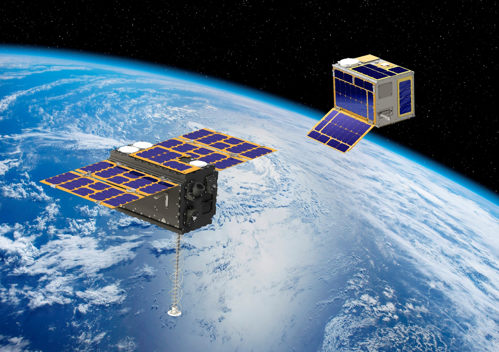
Protecting Large Capital Investments A key testing stage for large constellations is an In-Orbit Demonstration (IOD). An excellent example is the Celeste IOD mission, which flies an Anywaves L-band Quadrifilar Helix antenna, a GNSS All-Bands antenna and an S/C-Band antenna. For components like these, surviving severe thermal testing on the ground proves the business case to investors. Contracting a trustworthy manufacturer dramatically reduces the perceived risk and, consequently, the launch and in-orbit insurance premiums.
Speeding Up Certification and AIT Production certificates provide reassurance that tested hardware can be plugged directly into the payload. It eliminates the risk of Assembly, Integration and Testing (AIT) teams discovering a fault late in the timeline and having to disassemble the spacecraft. This agile hardware development means prime contractors get finalised, flight-ready designs in a much shorter timeframe, keeping launches on schedule.
With our recent merger, Anywaves is scaling up to bring space-qualified off-the-shelf products to the market. By mastering our thermal cycling procedures, we eliminate systematic flaws and guarantee performance, no matter how harsh the orbit.
Conclusion
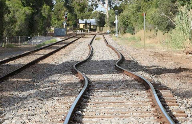
Credits: Adelaide Advertiser
We see the effects of thermo-mechanical stress on Earth every time an unprecedented heatwave hits the Northern Hemisphere. Think about railway tracks designed for a temperate climate: when temperatures suddenly soar, the steel absorbs the heat and expands. However, since it is bolted down with nowhere to go, the track bends and buckles. The steel doesn’t actually snap, but its geometry is ruined, bringing entire rail networks to a halt.
This is exactly how an RF payload fails in orbit. The antenna doesn’t have to snap in half to fail; it just has to warp a fraction of a millimetre out of alignment.
In an environment that shifts hundreds of degrees every 90 minutes, rigorous thermal cycling is the single biggest guarantee that a spacecraft will survive the conditions of space. Proving these components can withstand extreme swings between high and low temperatures saves time, money and effort, and ultimately prevents expensive satellites from becoming orbital debris.
As the commercial space industry accelerates, reliable testing at the start of the manufacturing chain is vital. It is the only way to successfully scale RF component production to the level of demand the space industry is currently gearing up for, proving that high-volume manufacturing doesn’t have to mean compromising on legacy-grade reliability.

