Quadrifilar Helix Antenna
Typical design targets — each antenna is designed to your specifications
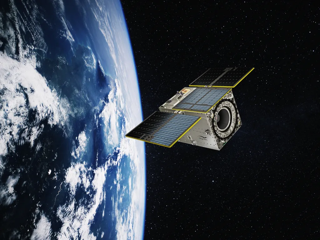
Uniform coverage. Deployable design. Built for LEO-PNT and IoT.
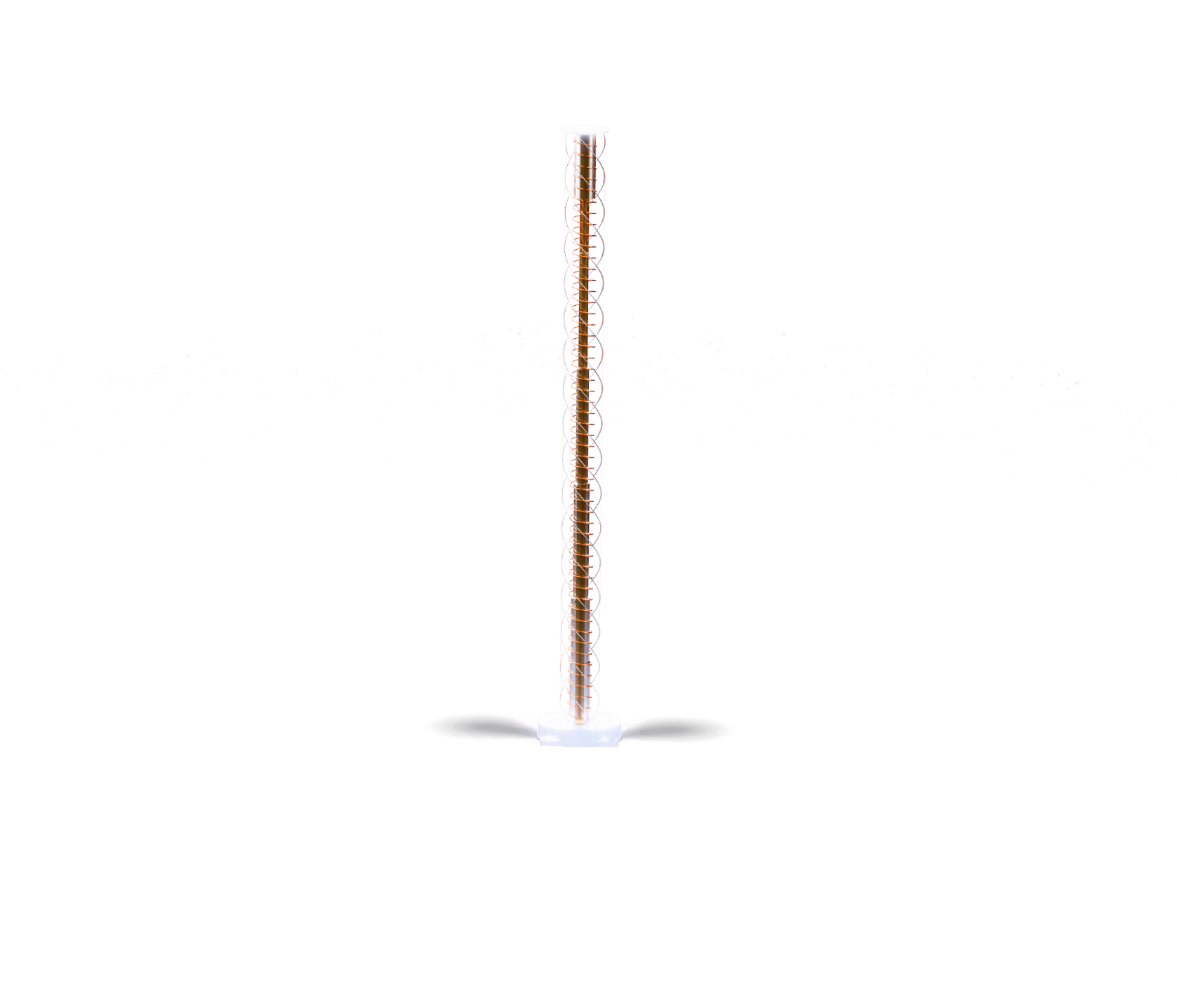
Deployable mast design — excellent stowed-to-deployed ratio in < 1.5 U
The deployable version of the Quadrifilar Helix Antenna uses a mast-based architecture that stows within less than 1.5 U of CubeSat volume for launch, then deploys to its full operational configuration in orbit. This excellent stowed-to-deployed ratio makes the deployable version the right choice for volume-constrained platforms where the antenna’s deployed size would otherwise prevent integration. Once deployed, the helix structure provides the full isoflux radiation pattern required for LEO-PNT, IoT or data relay operations.
Isoflux radiation pattern — uniform signal strength from zenith to horizon
An isoflux pattern is a radiation pattern specifically engineered to compensate for the path length difference between a LEO satellite and ground users at different elevation angles. A user directly below the satellite (short path) receives stronger signal than one near the horizon (longer path), which would result in non-uniform coverage if a standard hemispherical pattern were used. The Quadrifilar Helix Antenna’s isoflux pattern deliberately increases gain towards lower elevation angles to compensate for this path loss difference, providing a consistent received signal level across the entire footprint for all ground users simultaneously.
Qualified for LEO — vibration, shock and thermal vacuum tested
Both the deployable and fixed versions of the Quadrifilar Helix Antenna undergo a complete qualification campaign covering vibration testing, shock testing, and thermal vacuum cycling — the three test types that together address the primary mechanical and thermal failure modes of space-qualified hardware. This qualification campaign is mandatory for LEO-PNT and IoT constellation programmes that require demonstrated reliability over multi-year mission lifetimes. Customised acceptance tests are available to match the specific requirements of each customer programme.
Isoflux coverage antenna for LEO-PNT, IoT and data relay constellations
The Anywaves Quadrifilar Helix Antennas are custom-designed payload antennas for LEO satellites requiring uniform coverage across their ground footprint. Available in deployable (mast-based, stowed to less than 1.5 U) and fixed versions, they provide an isoflux radiation pattern — a gain profile that increases towards the horizon to compensate for greater path loss at low elevation angles — ensuring consistent signal quality for all ground users within the satellite’s coverage area simultaneously. This makes them the antenna of choice for LEO-PNT navigation transmitters, IoT connectivity payloads, and data relay missions.
Operating from UHF to S-band (custom frequency per project), the antennas provide single-circular polarization with a ~10% fractional bandwidth per frequency version. Built with flight-proven space-qualified materials and processes, they undergo a full qualification campaign (vibration, shock, thermal vacuum cycling) with customised acceptance tests on flight models. All parameters — frequency, isoflux gain profile, dimensions — are defined jointly with the customer. ITAR Free.
Requirement Definition
At Anywaves, we specialise in delivering custom-made antennas tailored to meet your unique requirements. Our expertise allows us to understand your specific needs and translate them into antenna specifications. We work closely with you to identify key parameters such as frequency bands, gain, beamwidth, mechanical constraints, and environmental considerations. Our team of experienced engineers collaborates with you throughout the process, ensuring that the antenna design aligns precisely with your application’s demands.
Project Management
Our experienced space project managers are skilled in coordinating all aspects of your custom-made antenna project, from initial concept to final delivery. With meticulous planning, effective communication, and diligent resource allocation, we ensure that your project stays on track through key milestones (PDR, CDR, TRR, TRB…). Our project management expertise enables us to navigate complex challenges, mitigate risks, and provide you with regular updates on project progress.
Technical Expertise
Our team of skilled engineers has extensive experience in antenna design and development, as well as in the space and defence industries. We leverage the latest tools and technologies to develop innovative antenna solutions that meet even the most complex challenges. With our technical expertise, we optimise key parameters such as gain, bandwidth, radiation pattern, and impedance matching to deliver antennas that excel in your specific application, following an extensive testing process to mitigate risks throughout the project.
Extensive Documentation
In addition to our standard EIDP package, we deliver throughout the project all the design justification you may need: RF, mechanical, thermal and radiation analyses; test plans; test reports. We make sure to deliver documentation that adds value to your project and guarantees that your antenna is compliant with your requirements.

Tell us your orbit and coverage requirements. We’ll design the isoflux pattern.
Share your constellation altitude, frequency band and ground coverage target. Our RF engineers will design a Quadrifilar Helix Antenna — deployable or fixed — with the right isoflux profile for uniform signal distribution across your footprint.
Questions & Answers
-
What is a quadrifilar helix antenna?
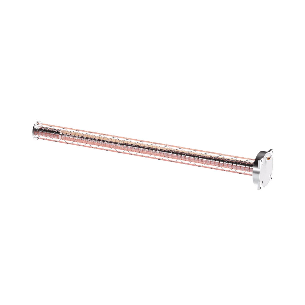
A quadrifilar helix antenna (QFH) is a type of circularly polarized antenna formed by four helical conductors wound symmetrically around a common axis, fed in quadrature (90° phase shifts between adjacent elements). The four-helix arrangement creates a cardioid or isoflux radiation pattern that is naturally circularly polarized — making it well-suited for satellite communication links where Faraday rotation and changing signal arrival angles require polarization stability. The helix architecture also provides a compact radiating structure that can be wound around a deployable mast for stowage, then extended to its operational height in orbit, combining excellent electrical performance with a small stowed volume.
-
What is an isoflux radiation pattern and why does it matter for LEO-PNT and IoT constellations?
An isoflux radiation pattern is a specially shaped gain profile designed to deliver approximately equal received signal power to all ground users within the satellite’s coverage footprint, regardless of their position relative to the satellite’s nadir. In a LEO orbit, a user directly below the satellite (at zenith) is much closer than a user near the edge of the footprint (at low elevation angles), and would therefore receive much stronger signal if a standard hemispherical antenna were used. An isoflux pattern compensates by gradually increasing gain towards the horizon — so that the higher gain towards distant users offsets their greater path loss, resulting in a uniform received signal level across the full coverage area. For LEO-PNT constellations and IoT connectivity payloads, this uniformity is critical: it ensures that all users within the satellite’s footprint can receive the service simultaneously without some being over-served and others under-served.
-
What is the difference between the deployable and fixed versions?
Both versions provide the same isoflux radiation pattern and RF performance. The difference is purely mechanical. The fixed version is a rigid antenna structure mounted directly on the satellite panel — simpler, lighter, and with no moving parts, but occupying its full deployed volume at all times. The deployable version uses a mast-based mechanism that stows the helical elements compactly during launch (within less than 1.5 U of CubeSat volume), then extends to the operational height in orbit through a deployment mechanism. The deployable version is the right choice when the antenna’s deployed dimensions exceed the available panel space on the satellite body, or when the stowed volume constraint is the binding integration driver.
-
What frequency bands are available?
The Quadrifilar Helix Antenna range covers UHF to S-band, with each version designed for a specific frequency within that range. Typical frequency targets for LEO-PNT include VHF/UHF (around 400 MHz, used in the original Doppler-based LEO-PNT systems), L-band (around 1.2–1.6 GHz, used in modern GNSS-based LEO-PNT and IoT services), and S-band (around 2–2.5 GHz, used in S-band IoT constellations such as those operating in the 2.4 GHz ISM band or satellite mobile services). The exact frequency, fractional bandwidth and isoflux gain profile are all defined jointly with the customer based on the specific spectrum allocation and link budget of the mission.
-
How does the Quadrifilar Helix Antenna relate to the other Anywaves payload antennas?
The Quadrifilar Helix Antenna occupies a unique position in the Anywaves payload antenna family: it is the only product specifically designed for isoflux coverage and LEO-PNT / IoT downlink applications. All other Anywaves payload antennas — the Slotted Waveguide, Reflectarray, Direct Radiating Array, Compact Wideband and Quad-Ridged Horn — are optimised for either high-gain directional links (SWG, Reflectarray, DRA) or wideband signal capture (Compact WB, Quad-Ridged Horn). The QFH is the transmit-side complement to the Anywaves GNSS All-Bands Antenna: while the GNSS antenna receives navigation signals on the satellite, the QFH transmits navigation or IoT signals to users on the ground, from the same LEO-PNT platform.
Quadrifilar helix antenna: isoflux coverage for LEO-PNT and IoT constellations
Anywaves’ Quadrifilar Helix Antennas are custom-designed LEO-PNT payload antennas for satellite constellations requiring uniform ground coverage. Available in deployable (mast-based, stowed to less than 1.5 U) and fixed versions, they provide an isoflux radiation pattern in single-circular polarization (LHCP or RHCP) across UHF to S-band frequencies with approximately 10% fractional bandwidth per version. The isoflux gain profile increases towards the horizon to compensate for greater path loss at low elevation angles, ensuring consistent received signal quality for all ground users within the satellite’s footprint simultaneously.
Applications include LEO-PNT navigation transmitters, IoT connectivity payloads, and data relay missions. Built with space-qualified materials and flight-proven processes. Qualification campaign includes vibration testing, shock testing, and thermal vacuum cycling. Customised acceptance tests available. All parameters (frequency, isoflux profile, deployed dimensions) defined jointly with the customer. TRL 6. ITAR Free.