High Gain X-Band Antenna
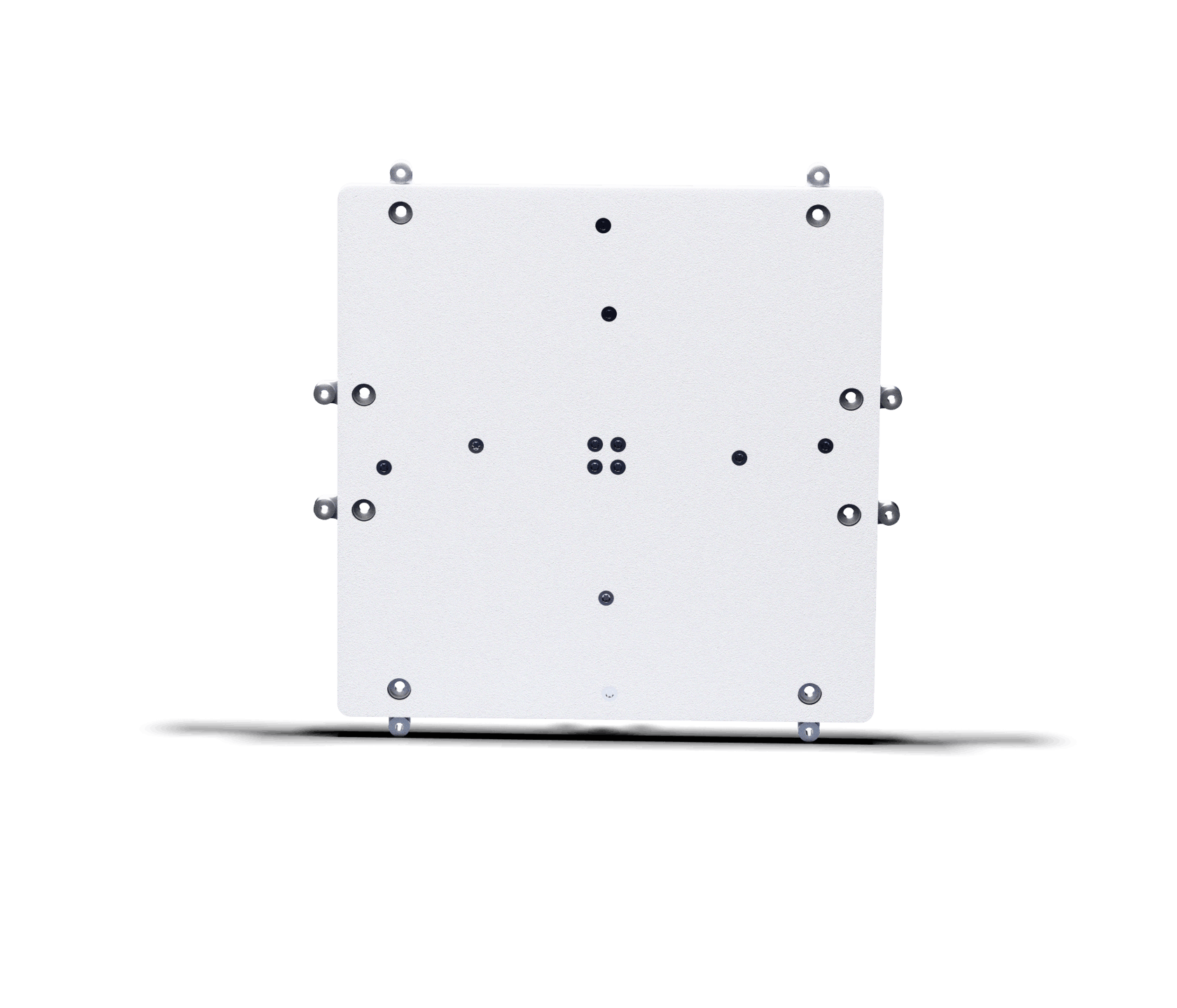
Technical specifications
Maximum X-Band gain for the most data-intensive missions.
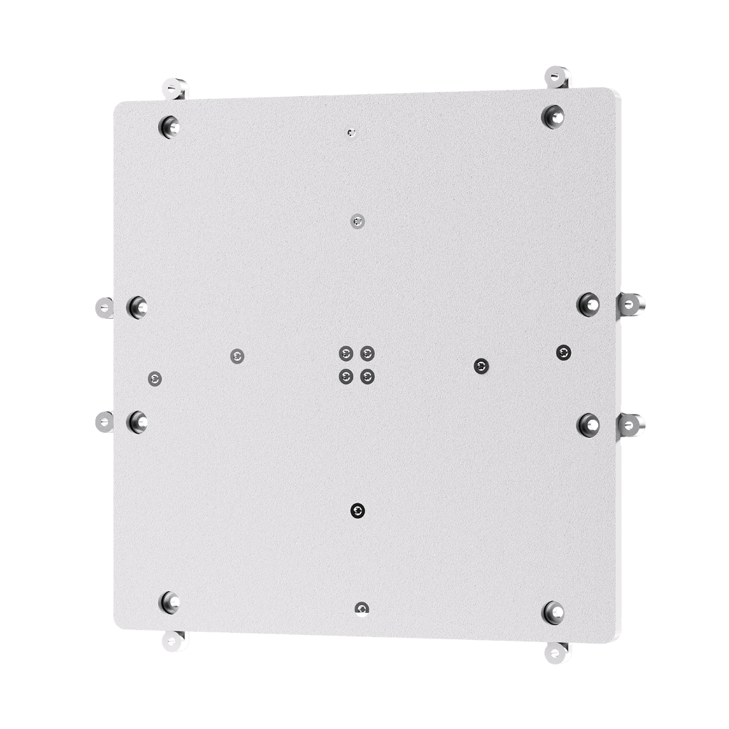
> 20 dBi boresight gain — the highest in the Anywaves X-Band range
The High Gain X-Band Antenna delivers a realized gain exceeding 20 dBi at 8.2 GHz, achieved through a large 200 × 200 mm aperture that concentrates RF energy into a narrow 9° pencil beam. This level of gain — 5 dBi more than the Compact X-Band Antenna — translates directly into a significantly improved link budget and higher achievable data rates, making it the right choice for Earth observation or remote sensing missions with the most demanding payload downlink requirements.

~9° HPBW pencil beam with <1 dB axial ratio at ±7.5°
The antenna’s Half Power Beam Width of approximately 9° (±4.5° in all planes) produces a highly directive pencil beam that maximises radiated power towards the ground station during the downlink window. The axial ratio stays below 1 dB within ±5° of boresight, ensuring excellent circular polarization purity and minimising losses due to Faraday rotation. This narrow beam requires accurate nadir or ground-station pointing from the spacecraft ADCS during the downlink pass.
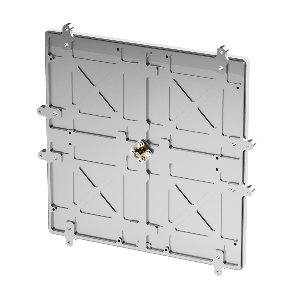
PEEK radome — thermal and ESD protection on a 16 mm profile
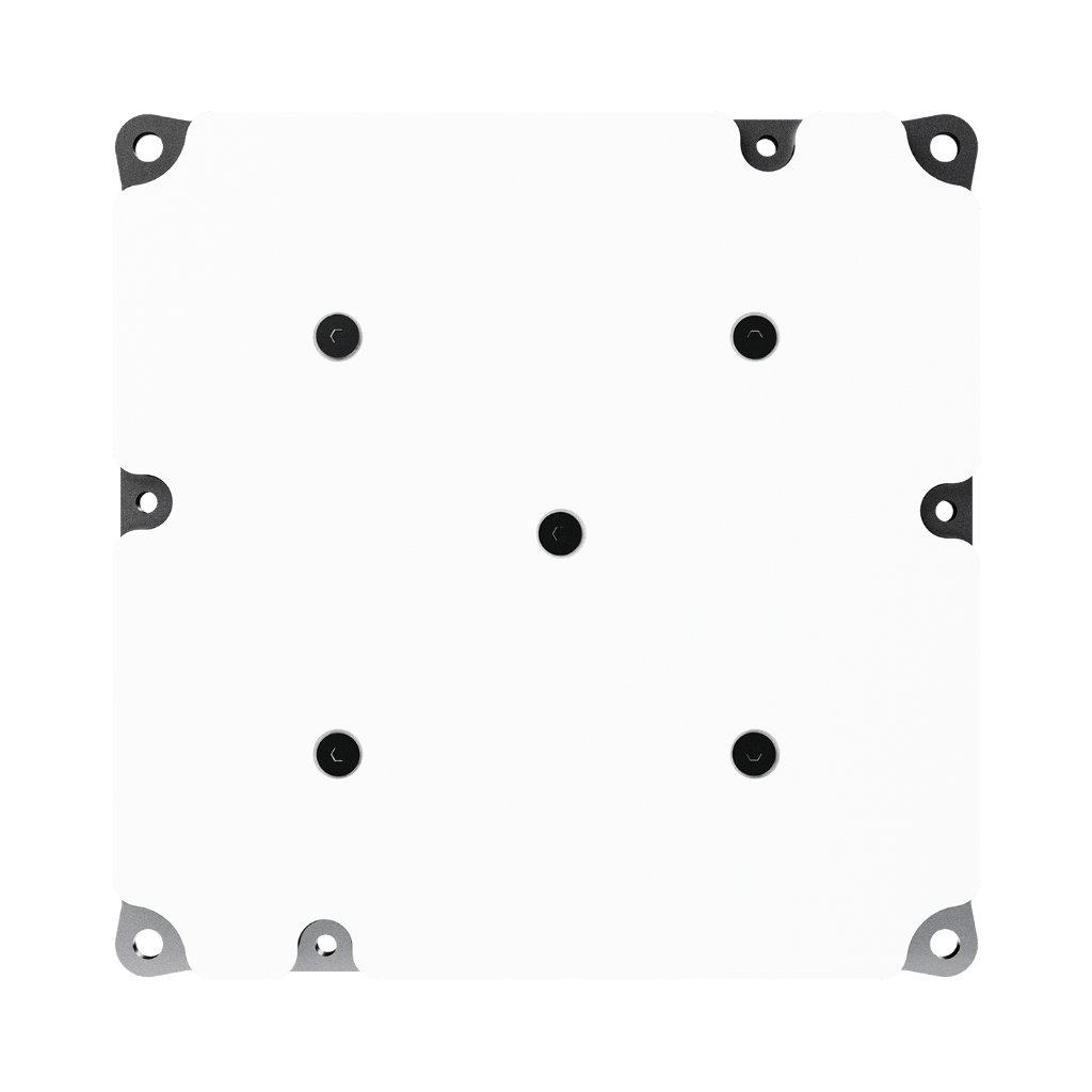
Featuring only a 200 × 200 mm aperture, the High Gain X-Band Antenna maintains a total height of only 16 mm, with less than 8 mm of protrusion above the satellite panel. Protected by a PEEK radome with SG121FD white paint on flight models, it withstands thermal extremes from −120°C to +120°C and prevents electrostatic discharge events — providing the same environmental resilience as the rest of the Anywaves X-Band antenna family, at a higher gain level.
The highest gain in the Anywaves X-Band range
The Anywaves High Gain X-Band Antenna exceeds 20 dBi of realized gain at 8.2 GHz — 5 dBi more than the Compact X-Band Antenna — through a 200 × 200 mm aperture that focuses all RF energy into a narrow 9° pencil beam. This gain level enables higher data rates with respect to the Anywaves Compact X-Band antenna, making it the right choice for Earth observation missions with large or high-resolution payloads generating large data volumes that must be downloaded within short LEO pass windows.
The antenna operates from 7.9 to 8.5 GHz (600 MHz bandwidth) in LHCP or RHCP, with a reflection coefficient better than −18 dB and an axial ratio below 1 dB at ±5°. Protected by a PEEK radome with anti-ESD coating, it maintains a low 16 mm profile with less than 8 mm of protrusion. Compatible with the Anywaves Test Hat for X-Band Antennas. Full acceptance testing on flight models. ITAR Free.

Complete EIDP
At the delivery of your antennas, you will receive a complete EIDP (End Item Data Package) including: RF acceptance test reports, ICD (Interface Control Document), Mechanical envelope, User Manual, Certificate of conformity.

In-Depth Engineering Support
During the full length of your antennas project, you’ll benefit from an in-depth and tailored support from our experienced engineers. They’ll answer all of your questions and ensure that our antennas meet your missions’ needs.

Further Testing Available On Demand
If needed, we can perform additional on-demand tests on your antennas to guarantee their performance in the specific environment and conditions of your spacecraft.

Specific Requests Analysis With Experts
In the case you need additional information and performance results, our experts can conduct complementary analysis based on your requirements (mechanical, thermal, radio-frequency performances on platform etc.).
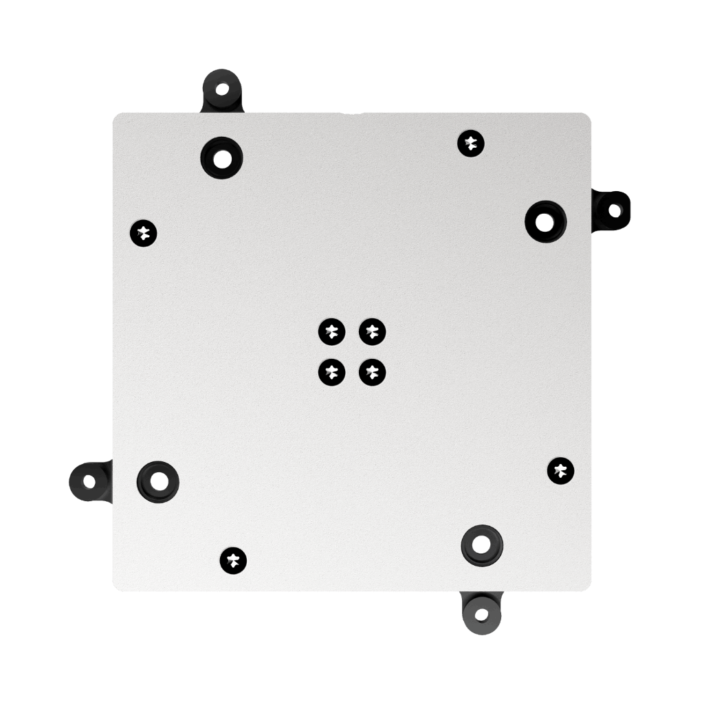

More gain. More data. Every pass.
Tell us about your payload volume and downlink requirements. Our engineers will help you maximise your X-Band data rate with the right antenna configuration.
Questions & Answers
-
When should I choose the High Gain X-Band Antenna over the Compact X-Band Antenna?
The choice between the two antennas comes down to link budget, footprint and pointing capability. The High Gain X-Band Antenna (>20 dBi, ~9° HPBW) provides approximately 5 dBi more gain than the Compact X-Band Antenna (15.5 dBi, ~20° HPBW), which translates into a significantly higher achievable data rate for the same ground station. However, it requires a larger panel footprint (200 × 200 mm vs 100 × 100 mm) and a much more precise ADCS pointing capability during the downlink pass, given its narrower beam. It is the right choice for missions with large payload data volumes — such as high-resolution EO imagery — and platforms capable of accurate nadir or ground-station pointing.
-
What does the ~9° Half Power Beam Width mean for operations?
A Half Power Beam Width of ~9° means the antenna gain stays within 3 dB of its 20 dBi peak across a cone of approximately ±5° from boresight. In practice, this means the satellite’s ADCS must maintain pointing accuracy of better than ±5° towards the ground station for the full duration of the downlink pass to guarantee at least half of the transmitted power is available for the communication link. Any pointing error beyond this will cause gain to drop rapidly. For comparison, the Compact X-Band Antenna has a ~20° HPBW, which is more forgiving of pointing errors but delivers lower gain, thus reduced data-rate.
-
What data rate can I achieve with the High Gain X-Band Antenna?
The achievable data rate depends on your full link budget — orbit altitude, ground station antenna size, modulation scheme and coding. The High Gain X-Band Antenna contributes more than 20 dBi to the link budget at 8.2 GHz, with a reflection coefficient better than −18 dB and an axial ratio below 1 dB within ±5°. For a typical LEO mission at 500 km altitude with a medium-size ground station (3–5 m dish), data rates of several Gbps are achievable depending on the RF chain. Contact our engineers for a tailored link budget assessment.
-
Is the High Gain X-Band Antenna compatible with the Anywaves Test Hat?
Yes. The High Gain X-Band Antenna is compatible with the Anywaves Test Hat for X-Band Antennas, allowing RF functional testing of the antenna while it is integrated on the spacecraft. This is particularly valuable for a high-gain antenna where verifying precise alignment with the spacecraft reference frame is critical before launch.
-
How does the High Gain X-Band Antenna compare to the Slotted Waveguide Array and Reflectarray antennas?
All three antennas target high-gain X-Band payload data downlink, but differ in architecture, gain level and integration complexity. The High Gain X-Band Antenna (>20 dBi) is a compact patch-based aperture that integrates directly on a satellite panel with standard M3 interfaces. The Slotted Waveguide Array and Reflectarray antennas offer potentially higher gain levels and different beam characteristics, but typically involve greater mechanical complexity. The right choice depends on your gain requirement, available panel surface and deployment constraints. Contact our engineers to compare options for your mission.
High gain X-Band antenna: >20 dBi pencil beam for maximum payload data rate
The Anywaves High Gain X-Band Antenna is a payload telemetry antenna delivering more than 20 dBi of realized gain at 8.2 GHz from a 200 × 200 mm aperture with a total height of 16 mm. Operating from 7.9 to 8.5 GHz (600 MHz bandwidth) in LHCP or RHCP, it generates a narrow ~9° Half Power Beam Width pencil beam with an axial ratio below 1 dB from 0° to ±5° and a reflection coefficient better than −18 dB. This gain level — the highest in the Anywaves X-Band data downlink range — enables maximum data throughput for Earth observation and remote sensing missions with large payload data volumes.
The antenna integrates on any satellite panel via 4 × M3 unthreaded holes, with a protruding height of less than 8 mm above the panel surface. It is protected by a PEEK radome with SG121FD qualified white paint on flight models, providing thermal resistance (−120°C to +120°C qualification range) and electrostatic discharge protection. Acceptance testing (RF, mechanical and thermal) is included on all flight models. Compatible with the Anywaves Test Hat for X-Band Antennas. ITAR Free.
