Direct Radiating Array Antenna
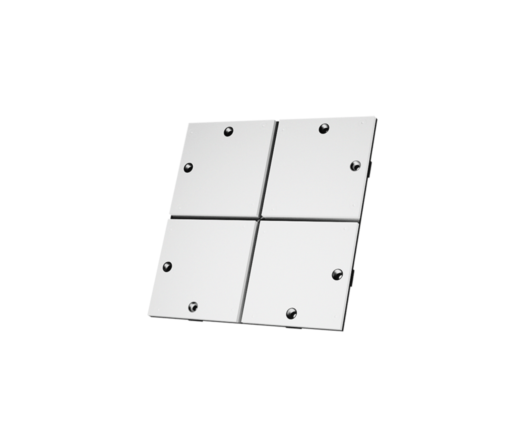
Typical design targets — each antenna is designed to your specifications
Custom Ka-band payload antenna with high power handling and scalable gain
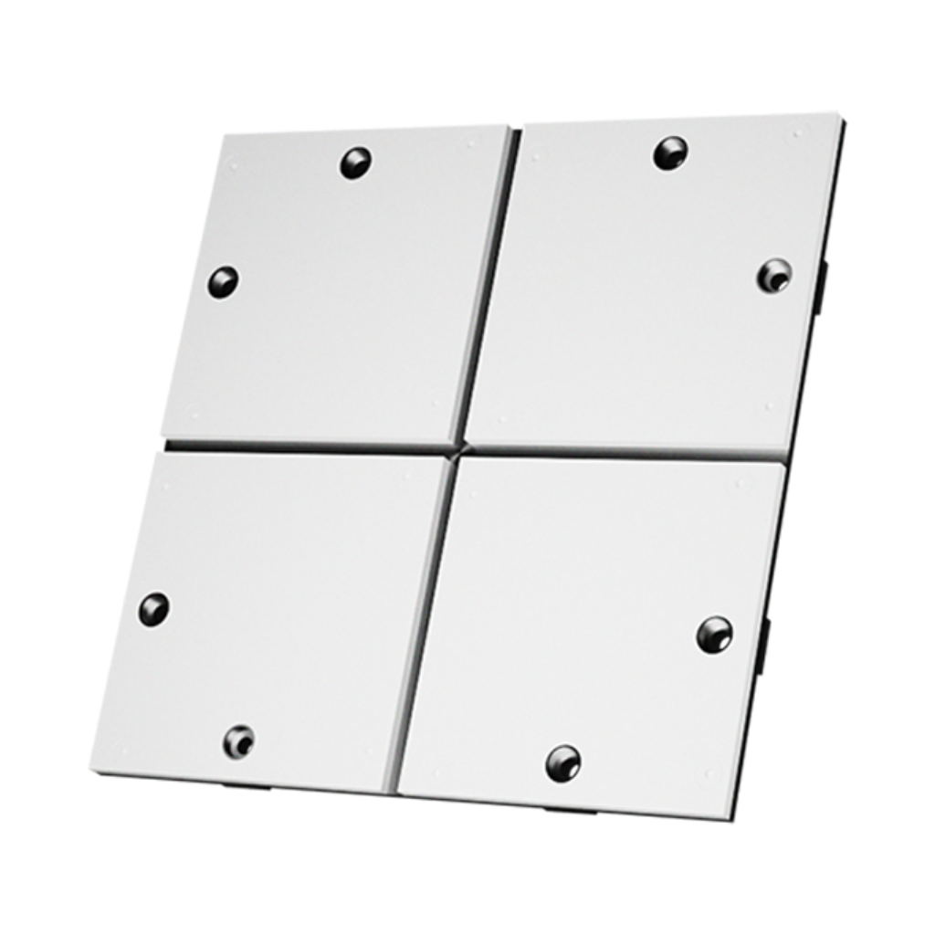
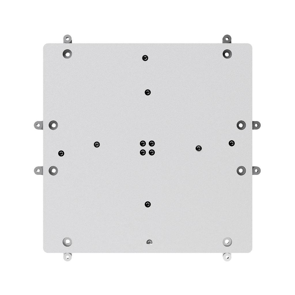
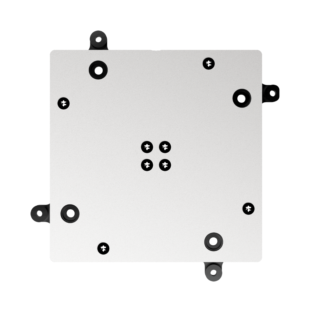
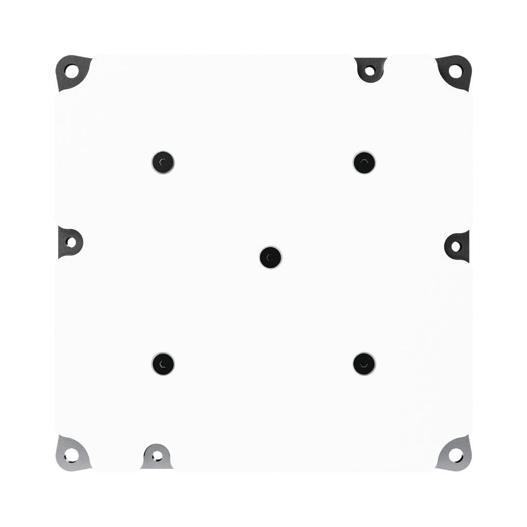
The Anywaves Direct Radiating Array Antenna is a custom-designed, high-gain flat antenna solution for satellite payload applications in Ku and Ka band, where high power handling and a low profile are the primary constraints. With a scalable patch array architecture delivering gains above 30 dBi within a 10% fractional bandwidth, it addresses the Ka-band link budget requirements for payload telemetry downlinks and inter-satellite link communications — applications where conventional patch arrays typically fail due to power handling limitations.
The antenna maintains first sidelobe levels of approximately 15 dB, ensuring clean beam quality alongside high gain. Its total profile thickness is less than 15 mm without the connector. Available in LHCP or RHCP. Protected by a space-qualified white paint radome for ESD protection and thermal stability. All parameters — frequency, gain, footprint, beam characteristics — are defined jointly with the customer and tailored to each mission. Qualification campaign included (mechanical vibration, thermal vacuum cycling, power-handling testing). ITAR Free.

Requirement Definition
At Anywaves, we specialise in delivering custom-made antennas tailored to meet your unique requirements. Our expertise allows us to understand your specific needs and translate them into antenna specifications. We work closely with you to identify key parameters such as frequency bands, gain, beamwidth, mechanical constraints, and environmental considerations. Our team of experienced engineers collaborates with you throughout the process, ensuring that the antenna design aligns precisely with your application’s demands.

Project Management
Our experienced space project managers are skilled in coordinating all aspects of your custom-made antenna project, from initial concept to final delivery. With meticulous planning, effective communication, and diligent resource allocation, we ensure that your project stays on track through key milestones (PDR, CDR, TRR, TRB…). Our project management expertise enables us to navigate complex challenges, mitigate risks, and provide you with regular updates on project progress.

Technical Expertise
Our team of skilled engineers has extensive experience in antenna design and development, as well as in the space and defence industries. We leverage the latest tools and technologies to develop innovative antenna solutions that meet even the most complex challenges. With our technical expertise, we optimise key parameters such as gain, bandwidth, radiation pattern, and impedance matching to deliver antennas that excel in your specific application, following an extensive testing process to mitigate risks throughout the project.

Extensive Documentation
In addition to our standard EIDP package, we deliver throughout the project all the design justification you may need: RF, mechanical, thermal and radiation analyses; test plans; test reports. We make sure to deliver documentation that adds value to your project and guarantees that your antenna is compliant with your requirements.

Tell us your power budget and gain target. We’ll design the array.
Share your frequency band, gain specification, power level and platform constraints. Our RF engineers will design a Direct Radiating Array antenna to match your Ka-band payload mission requirements precisely.
Questions & Answers
-
What is a Direct Radiating Array and how does it differ from other high-gain antennas?
A Direct Radiating Array (DRA) is a flat antenna in which an array of radiating elements — typically patches or similar aperture-coupled elements — is fed directly from an underlying distribution network, without an intermediate waveguide structure or a separate reflector. RF power is fed to each element through a planar feed network, and each element radiates directly into space. This architecture sits between two other Anywaves payload antenna technologies: the Slotted Waveguide Array, which uses waveguide-based radiating slots for full-metal construction and higher power handling per unit area; and the Reflectarray, which uses passive phase-shifting elements illuminated by a separate feed horn to achieve very high gain from a large deployable aperture. The DRA offers a middle ground: a fully integrated, low-profile active aperture capable of gains above 30 dBi with 10% fractional bandwidth, specifically designed for high-power Ka-band transmit applications.
-
Why is high power handling important for Ka-band payload antennas?
Ka-band frequencies (26.5–40 GHz) suffer significantly higher free-space path loss than lower frequency bands. At 30 GHz, the path loss over a typical LEO-to-ground link distance is roughly 10 dB higher than at 10 GHz. To maintain a viable data link under these higher losses, the satellite’s Ka-band transmitter must operate at higher power levels than an equivalent X-band system. This high power must be handled by the antenna without causing thermal damage, multipaction, or dielectric breakdown. The Anywaves Direct Radiating Array is specifically designed for this environment: its architecture manages the thermal load from both RF power dissipation and orbital heating, and avoids the dielectric failure modes that limit power handling in conventional patch antennas.
-
What applications is the Direct Radiating Array Antenna designed for?
The Direct Radiating Array Antenna is designed for Ka-band and Ku-band satellite payload applications requiring gains above 30 dBi with robust power handling. Primary applications include Ka-band payload telemetry downlinks, where the antenna transmits mission data from an Earth observation or remote sensing satellite to a ground station at high data rates; and inter-satellite link (ISL) communications, where the antenna maintains a high-gain Ka-band link between satellites in a constellation. It is a custom product: frequency, gain, aperture size, power handling and beam characteristics are defined jointly with the customer for each mission.
-
How does the Direct Radiating Array compare to the Slotted Waveguide Array Antenna?
Both products are custom-designed high-gain flat payload antennas for Ku/Ka-band applications, but they use fundamentally different architectures with different trade-offs. The Slotted Waveguide Array is a full-metal product: it has no dielectric material in the RF path, giving it maximum power handling and intrinsic ESD immunity, within a profile below 10 mm. The Direct Radiating Array uses a patch-based architecture with a planar feed network, giving it slightly more flexibility in element design and array geometry at the cost of a slightly higher profile (below 15 mm) and the use of dielectric substrate material. The DRA is optimised specifically for Ka-band transmit applications where the power handling requirements are high but not at the extreme levels that would require a full-metal waveguide architecture. Anywaves engineers can guide the trade-off based on your specific power level, gain requirement and frequency.
-
What qualification tests does the Direct Radiating Array Antenna undergo?
Anywaves’ Direct Radiating Array Antennas go through a rigorous qualification campaign that includes mechanical vibration testing, thermal vacuum cycling, and power-handling testing. These three test types together cover the primary failure modes of Ka-band high-power antennas in space: structural failure under launch loads (vibration), thermal-mechanical fatigue from orbital temperature cycling (vacuum thermal), and RF-induced thermal or dielectric breakdown under sustained high-power operation (power handling). Acceptance tests are also performed on flight models and customised according to the customer’s specific requirements, with all test plans, procedures and reports included in the EIDP documentation delivered at the end of the project.
Direct radiating array antenna: custom Ka-band payload for high power handling
Anywaves’ Direct Radiating Array Antenna is a custom-designed, high-gain flat antenna solution for Ka-band and Ku-band satellite payload applications. Using a scalable patch array architecture, it achieves gains above 30 dBi within a 10% fractional bandwidth (LHCP or RHCP), with first sidelobe levels of approximately 15 dB. Specifically engineered for high RF power handling — the primary challenge in Ka-band payload transmit applications — it is designed for Ka-band payload telemetry downlinks and inter-satellite link (ISL) communications from LEO and GEO platforms.
Profile thickness is less than 15 mm without the connector. Protected by a space-qualified white paint radome for ESD protection and thermal stability. Fully scalable: footprint and gain are tailored per mission to meet link budget requirements. Qualification campaign includes mechanical vibration testing, thermal vacuum cycling and power-handling testing. All parameters (frequency, gain, aperture, power level) are defined jointly with the customer. ITAR Free.
