Test Hat for S-Band TT&C Antennas
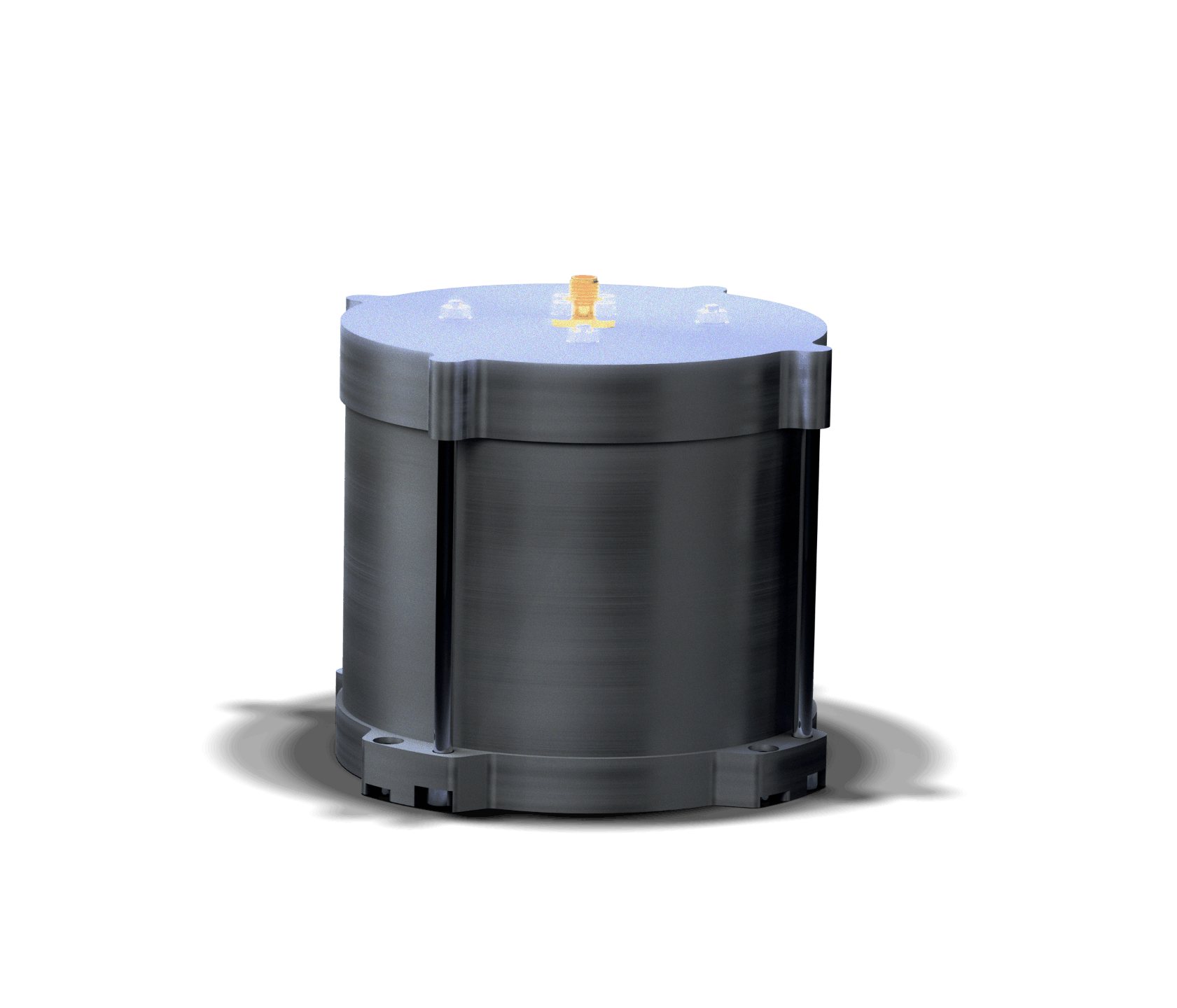
Technical specifications
S-Band TT&C testing. On the platform. No chamber.
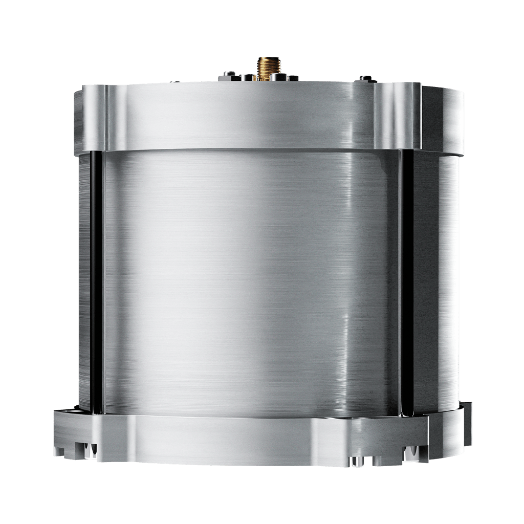
Single-part design — screws directly on the antenna, no bracket
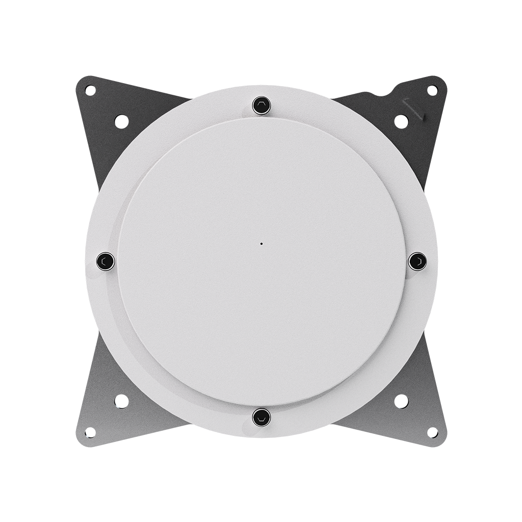
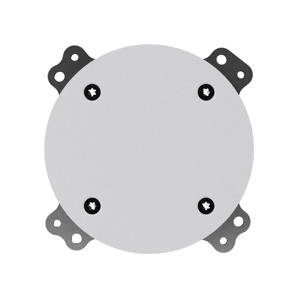
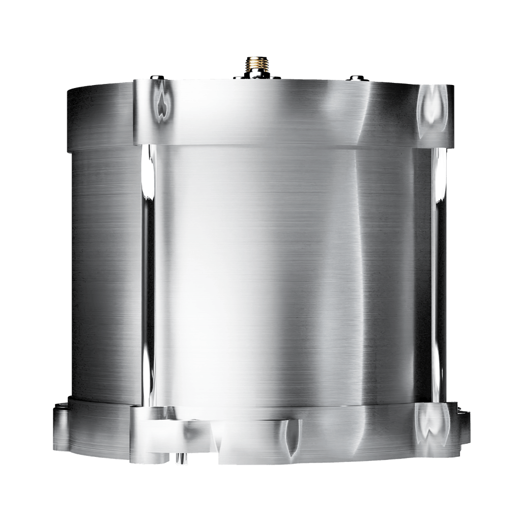
The Test Hat for S-Band TT&C Antennas consists of a cylindrical aluminium cavity lined with absorber material and terminated by an RF probe. Its single-part construction screws directly onto the S-Band TT&C Antenna via the 4 × M3 interface, with an oriented slot that ensures correct and reproducible positioning every time. This eliminates the need for a mounting bracket, minimises manipulation steps, and reduces the risk of antenna damage during testing — making setup and teardown quick and safe at every stage of the satellite’s AIT campaign.
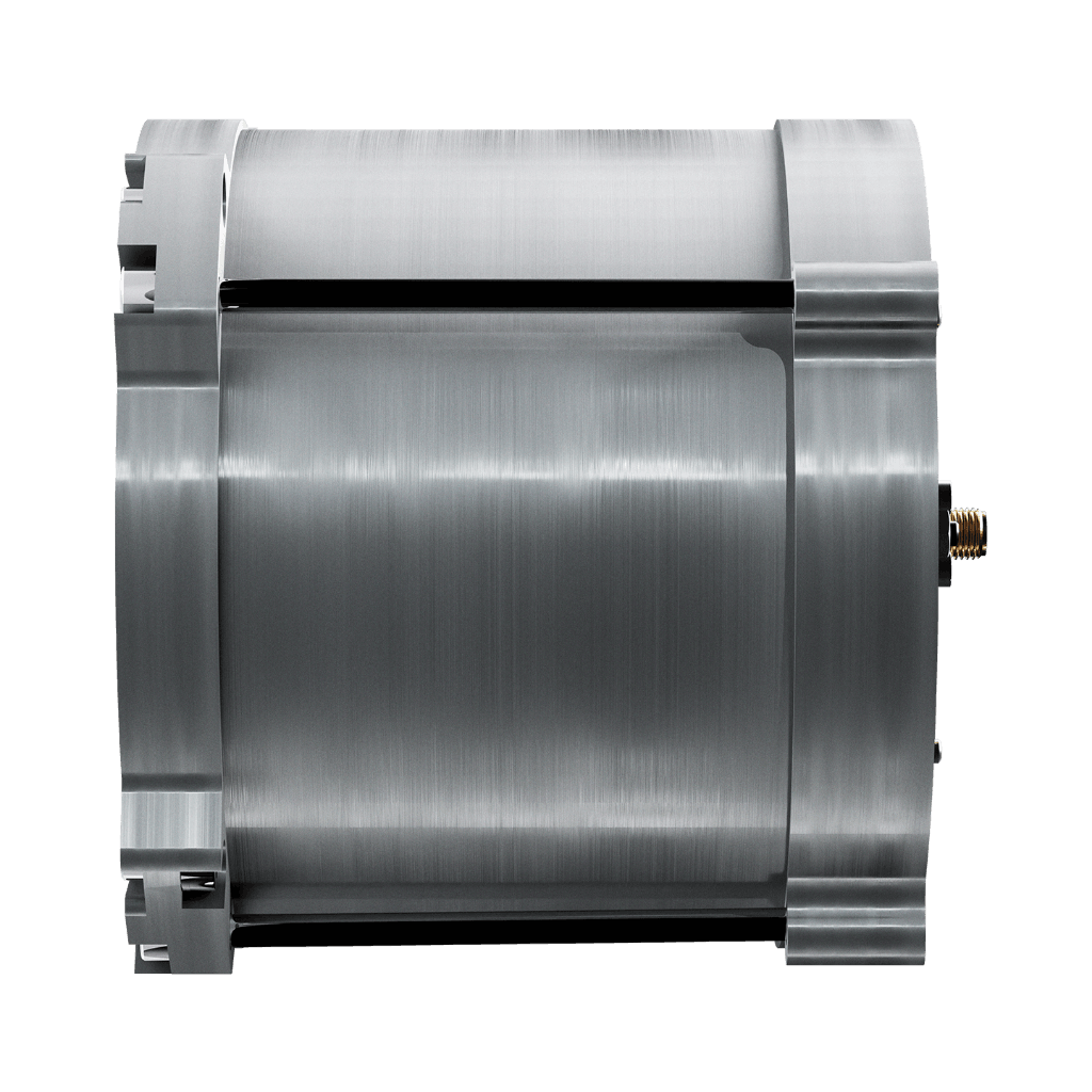
TVAC compatible — one tool for the full AIT campaign
Like its GNSS counterpart, the Test Hat for S-Band TT&C Antennas is qualified for use in thermal vacuum environments, with low outgassing properties that make it safe to leave installed inside a TVAC chamber throughout the test campaign. A single tool covers all S-Band TT&C RF verification needs from the assembly bench to TVAC, without requiring removal and reinstallation between test phases. Low RF leakage protects operators from radiation during the test.
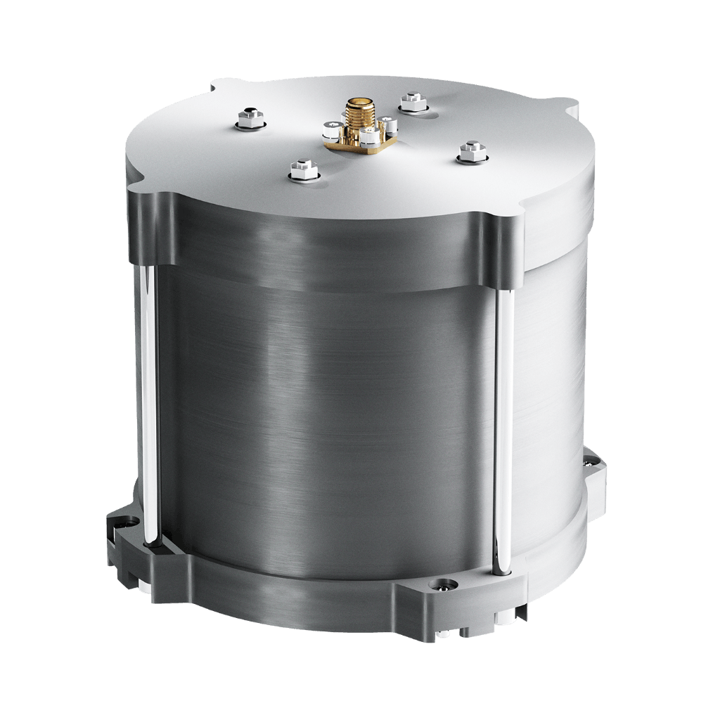
Compatible with LHCP and RHCP — works with the full S-Band TT&C Antenna family
The Test Hat for S-Band TT&C Antennas is compatible with both Left Hand and Right Hand Circular Polarization, making it suitable for use with all Anywaves S-Band TT&C antenna variants: the standard S-Band TT&C Antenna (available in LHCP, RHCP or dual-pol), the Compact S-Band TT&C Antenna, and the S-Band Launcher Antenna. A single test hat covers the entire S-Band TT&C antenna family, simplifying both procurement and inventory management across a satellite programme.
S-Band TT&C RF verification at every stage of integration
The Anywaves Test Hat for S-Band TT&C Antennas enables complete end-to-end RF testing of the S-Band TT&C antenna and transceiver chain directly on the satellite platform, from the assembly bench to final TVAC testing. By providing a stable −29 dB coupling across the full 1.98–2.29 GHz S-Band TT&C range, it eliminates the need for anechoic chamber measurements during integration, saving time and cost while delivering the reproducible measurement quality needed to validate S-Band TT&C performance before launch.
Its single-part cylindrical aluminium cavity screws directly onto the antenna with an oriented slot for repeatable positioning — no bracket, no tools, no risk of antenna damage. TVAC compatible with low outgassing. Compatible with both LHCP and RHCP polarization, covering the full range of S-Band TT&C Antenna configurations. Low RF leakage protects operators during the test. ITAR Free.
You might also like

Test your S-Band TT&C chain. On your platform. At every stage.
Tell us about your integration campaign and testing requirements. Our engineers will help you get reliable, repeatable RF measurements from your S-Band TT&C antenna without the anechoic chamber.
Questions & Answers
-
What is the Test Hat for S-Band TT&C Antennas used for?
The Test Hat for S-Band TT&C Antennas is a piece of ground support equipment (GSE) that enables end-to-end RF testing of the S-Band TT&C antenna and transceiver chain directly on the satellite platform, at any stage of the assembly, integration and test (AIT) campaign. By providing a controlled −29 dB RF coupling between the antenna aperture and the test equipment, it allows the integration team to inject a known RF signal into the TT&C system and verify the complete chain — uplink sensitivity, downlink output power, frequency accuracy and RF chain performance — without placing the satellite in an anechoic chamber.
-
Why are the coupling factor variations different for telecommand and telemetry bands?
The S-Band TT&C frequency range covers two distinct functions: telecommand (uplink, typically 2 025–2 110 MHz) and telemetry (downlink, typically 2 200–2 290 MHz). These two sub-bands have slightly different electromagnetic properties, which affect how uniformly the test hat couples signal across the band. The datasheet specifies coupling factor variation below 1 dB in the telecommand band and below 2 dB in the telemetry band — both acceptable for functional RF testing. The tighter specification in the telecommand band reflects its narrower frequency range and its primary role in receiver sensitivity testing.
-
Is this Test Hat compatible with the Compact S-Band TT&C Antenna?
Yes. The Test Hat for S-Band TT&C Antennas is compatible with the full Anywaves S-Band TT&C antenna family: the standard S-Band TT&C Antenna (LHCP, RHCP or dual-pol), the Compact S-Band TT&C Antenna, and the S-Band Launcher Antenna. All these antennas share the same mechanical interface (4 × M3 unthreaded holes) and the test hat is designed to work with both LHCP and RHCP polarization variants. A single test hat covers the entire product family. Note that a Test Hat compatible version of the antenna is required.
-
Can the Test Hat be used during TVAC testing?
Yes. The Test Hat for S-Band TT&C Antennas is qualified for use in thermal vacuum environments, with low outgassing properties making it safe to keep installed inside a TVAC chamber throughout the test campaign. Its qualification temperature range of −40°C to +70°C covers the standard TVAC test conditions used for satellite AIT. This means the same tool used for RF verification on the assembly bench can remain in place for TVAC, without any removal or reinstallation steps.
-
What is the difference between the Test Hat for S-Band TT&C Antennas and the Test Hat for GNSS All-Bands Antennas?
The two products share the same design concept — a single-part cylindrical aluminium cavity with absorber lining and RF probe, screwed directly onto the antenna — but are optimised for different frequency ranges and antenna families. The S-Band Test Hat covers 1.98–2.29 GHz (> 310 MHz bandwidth) for TT&C applications, and is compatible with both LHCP and RHCP polarization. The GNSS Test Hat covers 1.16–1.61 GHz (> 450 MHz bandwidth) for navigation applications, and is RHCP only. They are not interchangeable — each test hat is dimensioned and tuned for its specific antenna aperture and frequency range.
Test Hat for S-Band TT&C Antennas: on-platform RF testing for S-Band TT&C
The Anywaves Test Hat for S-Band TT&C Antennas is a ground support equipment (GSE) tool for performing end-to-end RF testing of the Anywaves S-Band TT&C antenna and transceiver chain directly on the satellite platform. Covering the full S-Band TT&C frequency range from 1 980 MHz to 2 290 MHz (> 310 MHz bandwidth), it provides a coupling factor of approximately −29 dB with variation below 1 dB in the telecommand band and below 2 dB in the telemetry band. Compatible with both Left Hand and Right Hand Circular Polarization.
Its cylindrical aluminium cavity, lined with absorber material and terminated by an RF probe, screws directly onto the S-Band TT&C Antenna via the 4 × M3 interface with an oriented slot ensuring repeatable positioning — no mounting bracket required. Compatible with the full Anywaves S-Band TT&C antenna family (S-Band TT&C Antenna, Compact S-Band TT&C Antenna, S-Band Launcher Antenna). Qualified for thermal vacuum environments (low outgassing, −40°C to +70°C). Low RF leakage protects operators during testing. Envelope: Ø 117 mm × 98 mm, mass 910 g (±10 g), SMA female connector (50Ω). ITAR Free.
