Test Hat for GNSS All-Bands Antennas
Technical specifications
End-to-end GNSS RF testing. On the platform. No chamber needed.
Single-part design — screws directly on the antenna, no bracket
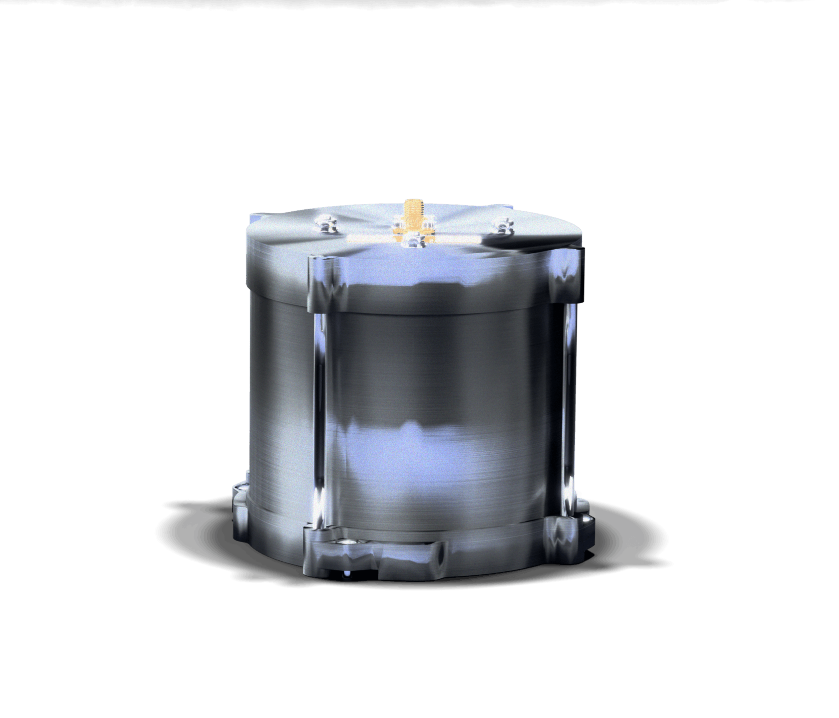
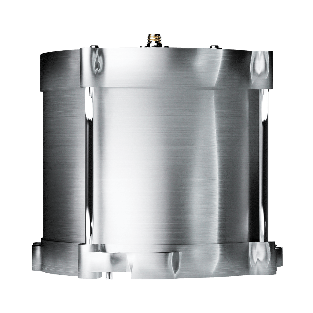
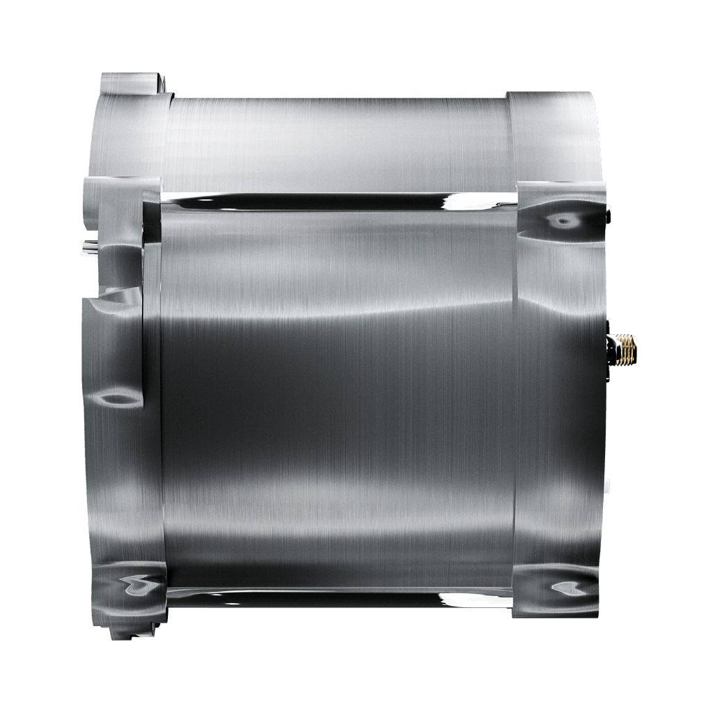
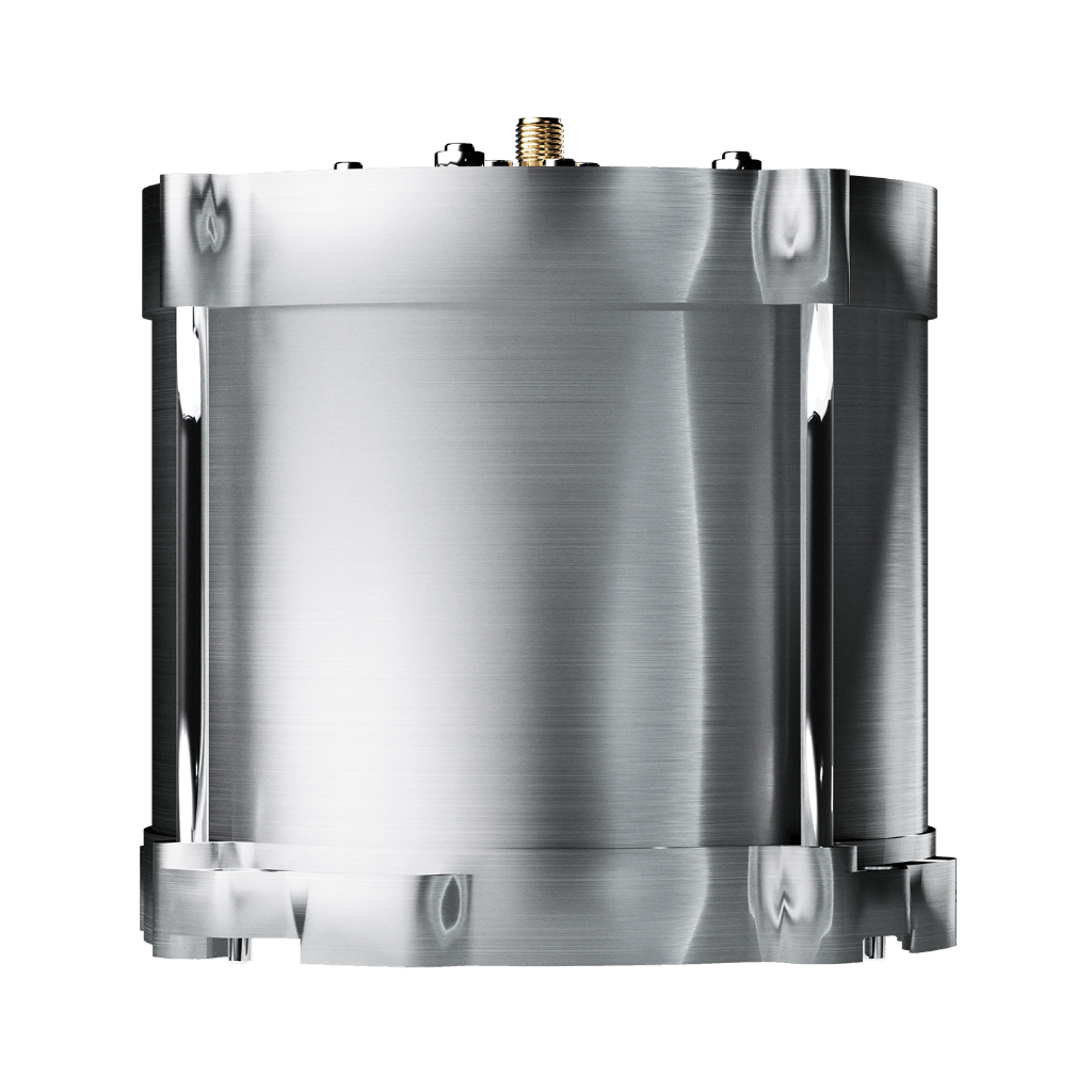
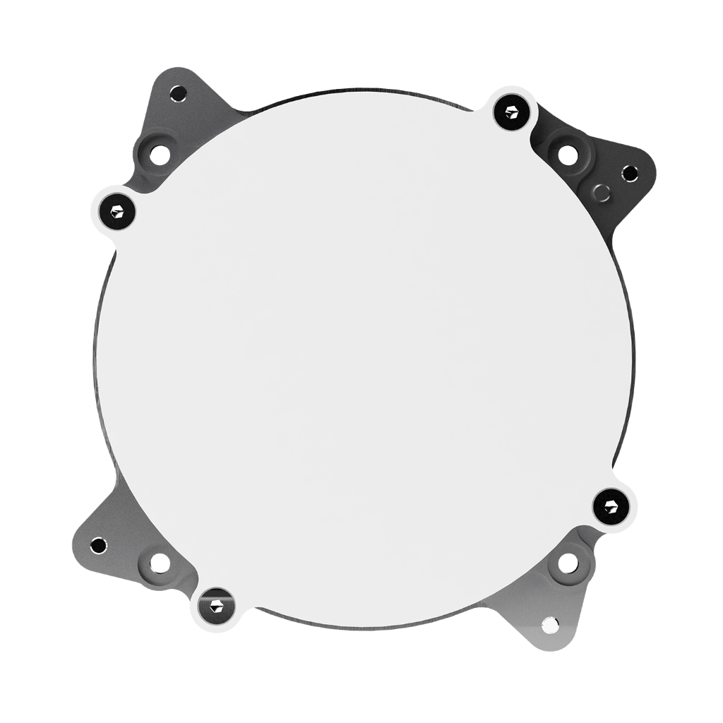
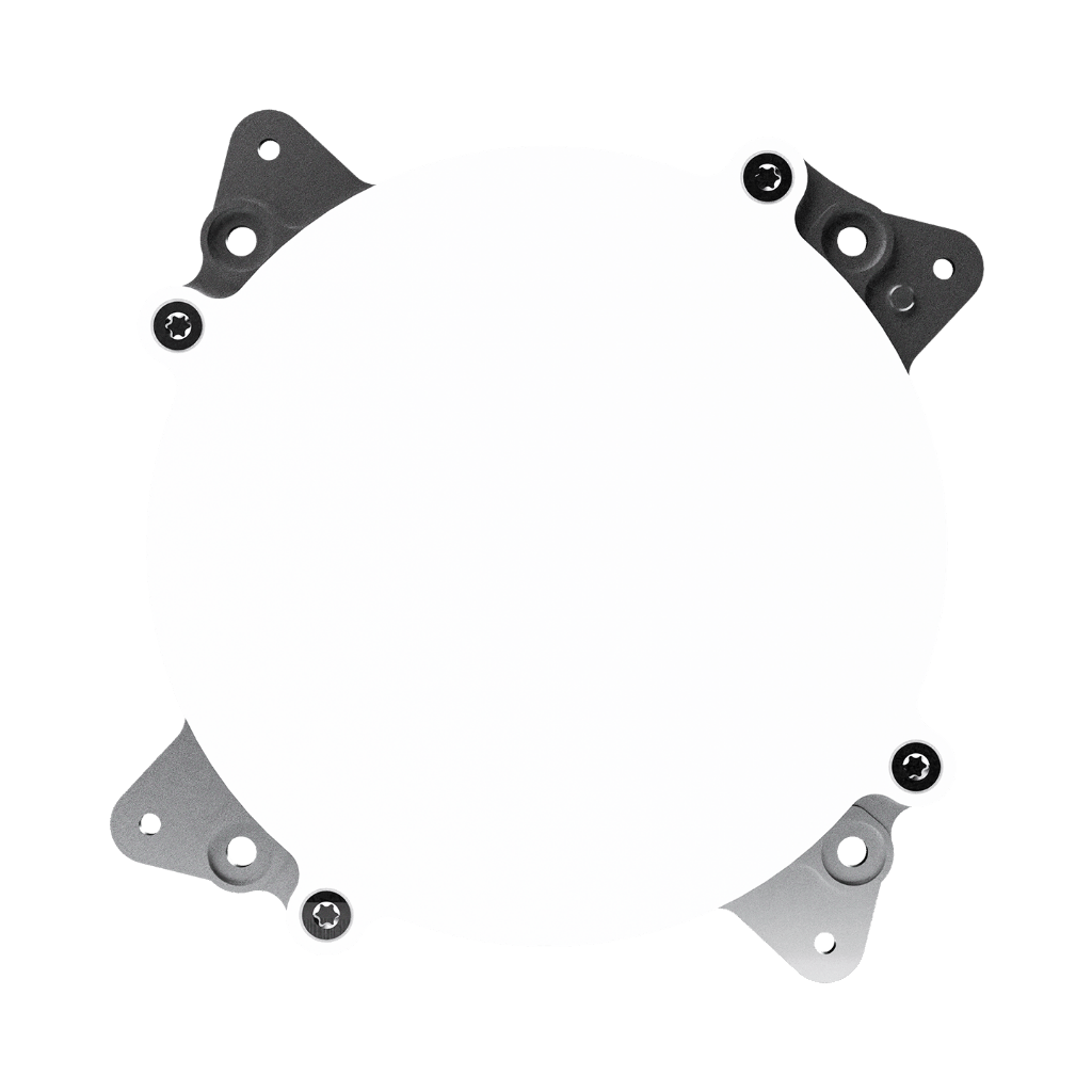
The Test Hat consists of a cylindrical aluminium cavity lined with absorber material and terminated by an RF probe. Its single-part construction eliminates the need for a mounting bracket on the satellite panel: it screws directly onto the GNSS All-Bands Antenna via the 4 × M3 interface, with an oriented slot ensuring correct positioning every time. This minimises manipulation steps, reduces the risk of antenna damage during testing, and makes mounting and dismounting safe and fast at any stage of integration.
TVAC compatible — test at every stage of the AIT campaign
The Test Hat is compatible with thermal vacuum environments, with low outgassing properties qualifying it for use inside a TVAC chamber. This means the same tool used for RF functional testing on the assembly bench can be kept in place for TVAC testing, without requiring removal and reinstallation between test phases. Combined with its low RF leakage design — protecting operators from radiation during the test — it covers every critical stage of a satellite’s AIT campaign with a single, simple tool.
Flat coupling across all GNSS bands — reproducible measurements every time
The Test Hat covers the full 1 160–1 610 MHz range with a coupling factor of approximately −29 dB and a variation of less than 1 dB across all lower GNSS bands (L2/L5, E5a/E5b/E6, G2/G3, B2/B3) and less than 0.5 dB at the primary navigation bands (GPS L1, Galileo E1, GLONASS G1, BeiDou B1). This flat coupling response ensures that measurements taken with the Test Hat are directly comparable across test sessions, platforms and test campaigns — giving integration teams consistent, reliable RF characterisation data throughout the satellite programme.
RF chain qualification without the anechoic chamber
The Anywaves Test Hat for GNSS All-Bands Antennas enables complete end-to-end RF testing of the GNSS All-Bands Antenna and receiver chain directly on the satellite platform. By providing a stable −29 dB coupling across the full 1.16–1.61 GHz GNSS band, it replaces the need for anechoic chamber measurements during integration testing, saving time and cost while maintaining the measurement quality required to demonstrate full RF chain performance.
Its single-part, screwed design mounts directly on the antenna with an oriented slot for repeatable positioning — no bracket, no tools, no risk of antenna damage. TVAC compatible with low outgassing, it can be used across all AIT phases without removal. Low RF leakage protects operators during testing. Compatible with all GNSS All-Bands Antenna variants (standard, with LNA, L1/E1). ITAR Free.

Test your GNSS chain. On your platform. At every stage.
Tell us about your integration campaign and testing requirements. Our engineers will help you get reliable, repeatable RF measurements from your GNSS All-Bands Antenna without the anechoic chamber.
Questions & Answers
-
What is a Test Hat and what is it used for?
A Test Hat (also called a Test Cap) is a piece of ground support equipment designed to couple an RF test signal into or out of an antenna without radiating it into the surrounding environment. Anywaves’ Test Hat for GNSS All-Bands Antennas is used to perform end-to-end RF testing of the GNSS antenna and receiver chain directly on the satellite platform, at any point during the assembly, integration and test (AIT) campaign — without requiring the satellite to be placed inside an anechoic chamber. This saves time and cost while delivering reproducible, consistent RF measurements across all test phases.
-
How does the Test Hat work?
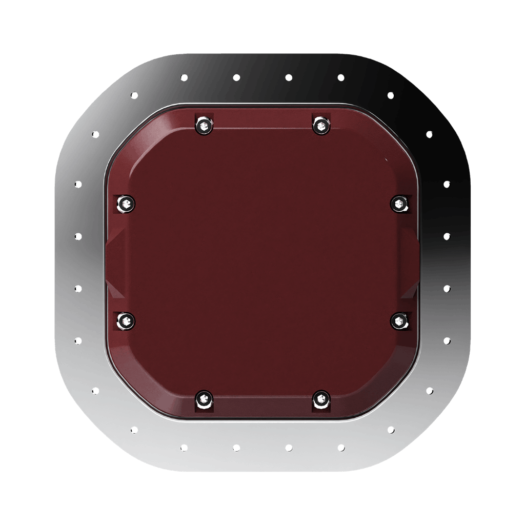
The Test Hat consists of a cylindrical aluminium cavity lined with absorber material and terminated by an RF probe. When screwed directly onto the GNSS All-Bands Antenna, it creates an enclosed RF coupling between the antenna’s radiating aperture and the test hat’s SMA output connector. The absorber lining prevents RF leakage to the outside environment while maintaining a stable, flat coupling factor of approximately −29 dB across the full 1.16–1.61 GHz GNSS band. The RF signal injected through the test hat connector appears at the GNSS receiver input, allowing full chain verification from the test equipment to the receiver.
-
What does the −29 dB coupling factor mean in practice?
The coupling factor is the ratio of the RF power injected at the test hat’s SMA connector to the RF power that appears at the GNSS antenna port. A coupling factor of −29 dB means that 29 dB less power reaches the antenna than what is injected into the test hat. In practice, this means a test signal injected at the test hat connector at a known power level will arrive at the GNSS receiver input at a predictable level, allowing the integration team to verify the receiver’s sensitivity, the LNA gain, and the full RF chain performance without relying on a live GNSS signal from space.
-
Can the Test Hat be used during thermal vacuum (TVAC) testing?
Yes. The Test Hat for GNSS All-Bands Antennas is qualified for use in thermal vacuum environments, with low outgassing properties that make it safe to leave inside a TVAC chamber throughout the test campaign. The same test hat used on the assembly bench can remain in place during TVAC, eliminating the need to remove and reinstall it between AIT phases. Its qualification temperature range of −40°C to +70°C covers typical TVAC test conditions.
-
Is the Test Hat compatible with the GNSS All-Bands Antenna with LNA Integrated Card?
Yes. The Test Hat for GNSS All-Bands Antennas is compatible with the standard GNSS All-Bands Antenna and also with the GNSS All-Bands Antenna with LNA Integrated Card, provided the LNA is powered during the test. The oriented slot in the test hat’s mounting interface ensures correct and repeatable positioning regardless of the antenna variant. Note that when testing with the LNA active, the DC supply must be connected through the Micro Sub-D connector of the integrated card, and the test setup must account for the LNA gain (typically 22 dB) when interpreting measured RF levels.
Test Hat for GNSS All-Bands Antennas: on-platform RF testing without an anechoic chamber
The Anywaves Test Hat for GNSS All-Bands Antennas is a ground support equipment (GSE) tool for performing end-to-end RF testing of the Anywaves GNSS All-Bands Antenna and receiver chain directly on the satellite platform. Covering the full 1 160–1 610 MHz GNSS frequency range (> 450 MHz bandwidth), it provides a stable coupling factor of approximately −29 dB with variation below 1 dB across all sub-bands (below 0.5 dB at GPS L1/Galileo E1/GLONASS G1/BeiDou B1), enabling reproducible RF chain measurements without an anechoic chamber.
Its cylindrical aluminium cavity, lined with absorber material and terminated by an RF probe, screws directly onto the antenna via the 4 × M3 interface — no mounting bracket required. A single-part design with an oriented slot ensures correct, repeatable positioning. Qualified for thermal vacuum environments (low outgassing, −40°C to +70°C) and compatible with all AIT phases. Low RF leakage protects operators during testing. Envelope: Ø 118.8 mm × 105.74 mm, mass 915 g (±5 g), SMA female connector (50Ω). ITAR Free.